Continue to Site

Welcome to our site!

Electro Tech is an online community (with over 170,000 members) who enjoy talking about and building electronic circuits, projects and gadgets. To participate you need to register. Registration is free. Click here to register now.

  • Welcome to our site! Electro Tech is an online community (with over 170,000 members) who enjoy talking about and building electronic circuits, projects and gadgets. To participate you need to register. Registration is free. Click here to register now.

Power Saving Devices - Do they actually work?

Status
Not open for further replies.

indecided

Member
My dad had a couple of "energy-saver" wallwarts plugged in today, one in each phase of the 240V power supply.

I was rather skeptical, but my dad rebutted by saying that the consumption went down on a multimeter demonstrated by the technichan... they measured the current draw before and after installing the devices, at the main switching box outside the house.

I myself am rather skeptical, as most of the motorized appliances in my house (ie fridges, freezers, split air cond units) are all about 5-6 years old and should be quite efficient..

However, I handled one of the devices, unplugged it and accidentally touched the live and neutral terminals while attempting to get a better look, and got a mild shock - something came to my mind then.

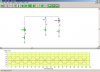
Could the current draw drop be due to the presence of a simple regulatory circutry and a large capacitor in the units? I'm pretty puzzled here, not to mention skeptical... If anyone has any experience with these things your comments are much appreciated :)

the product can be found at **broken link removed**
 
I'm rather dubious about the person selling you the device being the one proving how well it works?.

By the look of the website it simply provides power factor correction, so if you have devices that don't have good power factor consumption (usually inductive loads), and if the device works?, it could well correct your power factor.

Saving you money or not depends on how your electricity meter works, if it's a type that reads higher with poor power factor loads, it 'could' save you money.

Power factor correction is usually an industrial problem, with factories being penalised for poor correction - they usually go to great lengths to solve the errors - special 'power correction rooms' used to be common, with staff switching capacitors in and out of circuit to correct it.
 
Ive noticed that wallwart supplies get hot even when no current is being drawn. This is because there is some losses in the transformer (the coils do not have infinite DC resistance)

My phone charger is not hot when it is not being used. I was thinking that maybe it cuts off the primary of the transformer to mains when not being used. Either that or my wallwart is very very efficient.

Im just curious if anyone has ever heard of anything liek that?
 
zachtheterrible said:
Ive noticed that wallwart supplies get hot even when no current is being drawn. This is because there is some losses in the transformer (the coils do not have infinite DC resistance)

My phone charger is not hot when it is not being used. I was thinking that maybe it cuts off the primary of the transformer to mains when not being used. Either that or my wallwart is very very efficient.

Your phone charger is switchmode, FAR more efficient!.
 
zachtheterrible said:
My phone charger is not hot when it is not being used.
Could be a switching type?
I was thinking that maybe it cuts off the primary of the transformer to mains when not being used.
Unlikely. Any detection of "in use" or otherwise would surely take place in the secondary. If the primary were disconnected the detection circuitry wouldn't get power.
 
thats probably why. it is very small. Ive gotta read up on switchmode transformers.
 
indecided said:
My dad had a couple of "energy-saver" wallwarts plugged in today, one in each phase of the 240V power supply.

The fact that you recieved a shock after unplugging it, indicates that there is a capacitor inside. The purpose of this capacitor, as has been mentioned already, is simply for power factor correction.

I highly doubt the manafacturer's claims of "improving the equipment life-span" and "better performance".

Saving you money or not depends on how your electricity meter works, if it's a type that reads higher with poor power factor loads, it 'could' save you money.

Most domestic electricity meters (induction and electronic types) take account of power factor, and do not charge you extra for a poor power factor. However, if you are running a large factory which is on "maximum demand" metering, then power factor is a big concern, as a poor power factor will cost you money.

Overall, my assessment of this product is that it is a waste of time and money.
 
it all depends on the application. the type of load determines whether there will be considerable power saving or not. if the load is mainly inductive being overdriven by a greater than recommended voltage. or if the inductive loads (motors) run without load for greater periods of time then you will see some savings in your power bills.

even in the industries such devices do not show results claimed by the companies selling them. these guys are usually lacking technical knowledge and just know how to throw exotic words so as to impress the customers.

but do tell me if you do see a considerable power saving
 
Okay..thanks for the feedback..problem is that the guy went outside to test the load conditions before and after the devices were switched on, and my dad says that there was a drop in the consumption, measured on a multimeter... How how could that be then? PCF indeed at work?
 
indecided said:
my dad says that there was a drop in the consumption, measured on a multimeter... How how could that be then? PCF indeed at work?

Yes, you will see a drop in current - but not POWER. Your multimeter does not take into account PHASE ANGLE. It is important to note that you are billed for power, not current.

Power is calculated by the equation

P = VI cos (theta)
P is power
V is voltage
I is current
theta is the phase angle

cos (theta) is power factor.

For example, if your power factor previously was 0.5 (which is extremely low for a domestic situation), and you improve it to 1.0, your multimeter will show a halving of the current - but your power consumption hasn't changed.
 
Phasor,

thanks for the explanation.

So can I justify by saying that the mechanical measurement meters as below used by the electrical company to measure consumption use takes into account power in the sense of VI cos theta, whereas a multimeter shows current in other words, simply I without the other factors of V theta involved? Sorry but this is a bit to absorb for me, it would be nice if someone could re-write it, a bit more verbose :)

Mechanical means for measuring Watt-Hours are usually centered around the concept of the motor: build an AC motor that spins at a rate of speed proportional to the instantaneous power in a circuit, then have that motor turn an "odometer" style counting mechanism to keep a running total of energy consumed. The "motor" used in these meters has a rotor made of a thin aluminum disk, with the rotating magnetic field established by sets of coils energized by line voltage and load current so that the rotational speed of the disk is dependent on both voltage and current.
 
indecided said:
So can I justify by saying that the mechanical measurement meters as below used by the electrical company to measure consumption use takes into account power in the sense of VI cos theta, whereas a multimeter shows current in other words, simply I without the other factors of V theta involved?

Precisely. 8)
 
Thanks!

Just a last question... can one explain how the mechanical power measurement device 'takes this into account'? As in, the operation of the motor which operates the circular disk.

Phasor said:
indecided said:
So can I justify by saying that the mechanical measurement meters as below used by the electrical company to measure consumption use takes into account power in the sense of VI cos theta, whereas a multimeter shows current in other words, simply I without the other factors of V theta involved?

Precisely. 8)
 
well its not just the mechanical ones. there are also solid state energy and power meters.

in the mechanical energy meters there are two coils; pressure coil (PC) and current coil (CC) and the disk rotates due to current flow in both the coils. if you open up a mechanical energy meter you will see two coils having different thickness of wire.
 
A friend of mine saw the following setup/demonstration and he was pretty convinced that can not be right. However, he could not figure out how.

If you know how this is done, he would be happy.

Power(AC) is connect via an energy meter(W), one with a rotating disc visible, to two power sockets(S1 & S2) in the following fashion.

AC-->W-->S1-->S2

When an appliance is plugged into the first socket(S1), the energy meter disc starts rotating quickly.

Now the "energy saving" device is plugged into the socket S2, the rotating speed of the disc is visually observed to be slowed down. If the device is removed, the disc speeds up.

As the energy meter measure power, the device thus was shown to save power via the demonstration.
 
Yes, you will see a drop in current - but not POWER. Your multimeter does not take into account PHASE ANGLE. It is important to note that you are billed for power, not current.

Power is calculated by the equation

P = VI cos (theta)
P is power
V is voltage
I is current
theta is the phase angle

cos (theta) is power factor.

For example, if your power factor previously was 0.5 (which is extremely low for a domestic situation), and you improve it to 1.0, your multimeter will show a halving of the current - but your power consumption hasn't changed.

Does that mean that your appliance is consuming more power (meaning more efficient) than what it used to consume before the power factor correction because PFC would give max power by making adjusting the phase (power factor=cos 0=1.0)?
and why does the multimeter show halving of the current if the only thing that is corrected is the phase?
:?:
 
gastonanthony said:
Does that mean that your appliance is consuming more power (meaning more efficient)

No, the power consumed by the individual appliance does not change. Nor does the current to that individual appliance.

What you have to consider is that you have a multi-branch sub-circuit, with an inductive ("lagging") current flowing in the branch which the appliance is connected to.

By applying a capacitive ("leading") current flowing in another branch of the same circuit, the leading and lagging currents will cancel each other out at the origin of the circuit (before it branches)


and why does the multimeter show halving of the current if the only thing that is corrected is the phase?

Go back to the equation - if power is not changing, and we assume voltage does not change either, then 'I' must be inversely proportional to cos theta, in order for the equation to balance. Thus by increasing cos theta, 'I' must decrease proportionately.
 
oh, that's how it works!thanks, didn't quite understand the power factor correction topic in my past basic electrical circuit subject :oops: thanks again :D
 
To demonstrate - the screenshot of the simulation below. The small resistors are shunts to measure the current on the graph.

In the left branch, we have an inductive current - as represented by the red trace on the graph.

In the right branch, we have a capacitive current, almost, but not quite, equal to the inductive current, as represented by the blue trace.

Note that the inductive and capacitive currents are 180 degrees out of phase with each other.

Now, note the pink trace. This is the total circuit current. Note that it is much lower than either the inductive or capacitive currents.

If the two branch currents were exactly equal, the total circuit current would be ZERO.

(Of course, all this assumes that there is no resistive component in the loads, but in practise, there always is some resistance)
 

Attachments

  • capture_04252005_003902.jpg
    capture_04252005_003902.jpg
    51.1 KB · Views: 631
Phasor, do you think you could address this?

eblc1388 said:
A friend of mine saw the following setup/demonstration and he was pretty convinced that can not be right. However, he could not figure out how.

If you know how this is done, he would be happy.

Power(AC) is connect via an energy meter(W), one with a rotating disc visible, to two power sockets(S1 & S2) in the following fashion.

AC-->W-->S1-->S2

When an appliance is plugged into the first socket(S1), the energy meter disc starts rotating quickly.

Now the "energy saving" device is plugged into the socket S2, the rotating speed of the disc is visually observed to be slowed down. If the device is removed, the disc speeds up.

As the energy meter measure power, the device thus was shown to save power via the demonstration.
 
Status
Not open for further replies.

New Articles From Microcontroller Tips

Back
Top