Electro Tech is an online community (with over 170,000 members) who enjoy talking about and building electronic circuits, projects and gadgets. To participate you need to register. Registration is free. Click here to register now.
Welcome to our site! Electro Tech is an online community (with over 170,000 members) who enjoy talking about and building electronic circuits, projects and gadgets. To participate you need to register. Registration is free. Click here to register now.
I am building a power amplifier rated at 500 watt with +/- 80 volts supply. using sanken 2922 and sanken 1216 as power output transistor. how many power output devices are needed for each supply rail?
An amplifier that uses +/- 80V power supply has a max output of about 152V p-p. Then its power at clipping into 8 ohms is "only" 361W RMS.
It might produce 578W RMS at clipping into 4 ohms.
An ordinary 500W class-AB amplifier is about 55% efficient. So for an output of 500W the transistors dissipate about 410W. Each transistor can dissipate about 70W if the heatsink is huge and maybe 100W if the heatsink is big and there is a high velocity fan. 6 output transistors are needed if the heatsink is huge and there is no fan. 4 transistors are needed if the heatsink is big and there is a high velocity fan.
But most people don't play music at full blast all the time.
Never mind how many supply rails.
Use 4 transistors or 6 transistors so that 4 can dissipate 100W each with a fan or 6 can dissipate 70W each without a fan.
ah ok..
4 transistor this will be a double output stage, and triple output stage for 6 transistor, is it advisable to put a coil in the output? what is the purpose of it?
Never mind how many supply rails.
Use 4 transistors or 6 transistors so that 4 can dissipate 100W each with a fan or 6 can dissipate 70W each without a fan.
there are only two supply rail for +/- 80 volts supply. 4 output transistor means 2 transistor in each supply rail 2 transistor for the positive with respect to ground and 2 transistor for the negative with respect to ground. not including you driver transistor.
ah ok..
4 transistor this will be a double output stage, and triple output stage for 6 transistor, is it advisable to put a coil in the output? what is the purpose of it?
Never mind how many supply rails.
Use 4 transistors or 6 transistors so that 4 can dissipate 100W each with a fan or 6 can dissipate 70W each without a fan.
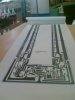
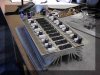
Heres a highly respected PA amplifier, well known for it's reliability and performance, it offers 700W per channel to 2 ohms, and 480W per channel to 4 ohms, and can be bridged if required to give 1400W to 4 ohms.
The Australian 1500W amplifier was drawn as a joke and was never built.
It will probably blow up until it is tweaked properly.
If it works then your 500W stripped version should also work.
The Australian 1500W amplifier was drawn as a joke and was never built.
It will probably blow up until it is tweaked properly.
If it works then your 500W stripped version should also work.
This site uses cookies to help personalise content, tailor your experience and to keep you logged in if you register.
By continuing to use this site, you are consenting to our use of cookies.