Electro Tech is an online community (with over 170,000 members) who enjoy talking about and building electronic circuits, projects and gadgets. To participate you need to register. Registration is free. Click here to register now.
Welcome to our site! Electro Tech is an online community (with over 170,000 members) who enjoy talking about and building electronic circuits, projects and gadgets. To participate you need to register. Registration is free. Click here to register now.
Mike,
Thanks.
I have two goals here. First I would like to get the circuit working. Second I would like to learn a little about electronics.
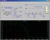
In looking at your diagram, I don't see R1.
Don
Again, thanks to all who offered help. I assembled mine per MikeMl's thumbnail (3 posts up). The circuit works fine. The "On " time is currently 24 minutes. I am sure I can get the time down within my parameters by trial and error lowering the ohmage of the discharge resistor, unless someone has some suggested calculated number to start.
Don
You guys are right on. Down to about 100K reduced the time to about 10 minutes. Although that would have been acceptable, I went down to 47K and the time went down to 6 minutes. Perfect.
I really appreciate everyone's help. This is a great forum
Don
Mike,
You had mentioned earlier that one should use a momentary switch to energize the capacitor, or at least that is what I thought you said. Is there any downside to letting that side be energized full time while the master switch is on, and just let the "timer" start when the master switch is turned off. In that case, the original switch to turn the light on would interrupt the power to the "points" side of the relay.
Don
That should work with one minor downside: the relay will be pulled in any time the master is on.
How about feeding the dome light slide switch to the top end of the relay coil AS WELL AS feeding power to the dome light through the relay contact? That way, the relay coil only comes on if the slide switch is closed. The power drawn from the master relay for the timing network is negligible.
Mike,
Thanks for the suggestion, but I there is a little information I had previously omitted (as I didn't think it was pertinent). That is, my plane actually has two cabin lights, one in front and one in back. That, I think, would require two timer circuits.
I don't think the fact that the relay is closed while the master is on should create a problem. The amperage draw should be very low, and I don't think that would create any appreciable wear on the points. Am I wrong in those assumptions.
Don
If you used a single timer and relay, you could use it to feed power to both the fore and aft cabin lights switches.
The sequence to get either cabin light on would be momentarily turn on the Master, optionally turn it off. That powers the relay for six minutes, allowing either of the cabin lights to be controlled by their respective switch. With Master off, if you walk away, the relay drops out six min after it was turned off. If a cabin light switch gets left on, then the cabin light will come on the next time you turn on the Master.
The Cabin lights are already fed directly from the battery through an existing Fuse/Breaker. Hook that circuit to the relay as shown.
Add a new fuse/breaker fed from the main bus (downstream from the Master Relay). AC43 requires that new circuit to be protected at the bus end. That supplies the charging current for the timing network.
Wire the two cabin light circuits downstream from the relay, as shown.
This site uses cookies to help personalise content, tailor your experience and to keep you logged in if you register.
By continuing to use this site, you are consenting to our use of cookies.