Electro Tech is an online community (with over 170,000 members) who enjoy talking about and building electronic circuits, projects and gadgets. To participate you need to register. Registration is free. Click here to register now.
Welcome to our site! Electro Tech is an online community (with over 170,000 members) who enjoy talking about and building electronic circuits, projects and gadgets. To participate you need to register. Registration is free. Click here to register now.
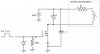
I am trying to use a power MOSFET as a switch to actuate the power supply to an exciter. I am lost as to how to determine the value of my decoupling capacitor.
Thanks.
Use a 10µF electrolytic and a 100nF ceramic capacitor in parallel - the ceramic is needed because it's better at higher frequencies than the electrolytic.
Thanks for that.
Is there any reason for these capacitor values? I thought that the capacitor values need to be determined based on the current through it and on the ripple voltage of the RL circuit.
Assuming the 42V is from a stabilised source and there's no hidden transformer and bridge rectifier, those values will do.
It's not important, you could just easily use a 22μF electrolytic and a 150nF ceramic capacitor. The capacitors just help to smooth the supply and remove load transients.
The 42V will be supplied from stable DC batteries - no transformer or rectifiers involved. I am thinking of having a PWM signal at the gate. I am still deciding about using a low-side gate driver or not? and also how would I determine the duty cycle needed for the PWM?
The aim is to control the output voltage of a synchronous gen with a PLC. It is assumed that the batteries will be charged 'separately' - i.e. not by the designed system
Automotive voltage regulators "sort of PWM" the field current of the alternator. The reason I say "sort of" is because the VR is nothing but a bang-bang "thermostat like" system: Turn off the field switch (usually a power transistor) if the bus (battery) voltage is > set point; turn on the field current if the bus (battery) voltage is < set point. It is the inductance (several H) of the field winding that creates the appearance of PWM.
If you hang a scope probe on the field connection to the alternator, you see a low frequency pulse signal that wanders between 25 to 100Hz, where the duty cycle of the ratio of on to off determines the average output current. Just like your house where the temperature is always increasing or decreasing, the bus voltage (and field current) is always increasing or decreasing around the set point.
The current through the field (rotor) is unipolar and always flows due to the smoothing effect of the field inductance. The average field current is a function of the duty cycle of the field voltage. The field voltage is either fully on (Battery voltage - VCEsat of the transistor switch) or fully off (0V).
Suppose if you pedal hard continuously you'll go 25mph but if you pedal just as hard but have a break for 30 seconds every minute you'll only go 15mph; the inertia is the inductance and the ratchet on your bike's gears is the free-wheel diode.
That makes sense. My understanding is that the battery will always be at 42V, and the current is going to vary according to the load on the exciter. If I'm correct, my gate signal will be in continuous mode then???
If you use a "linear regulator" to control the field (exciter) current, then the FET will be dissipating many Watts. If your switch the field on/off at a few tens of Hz, the duty cycle ratio (On time)/ (On time + Off time) will control the alternator output current, and the losses in the FET switch will be small.
That makes sense. My understanding is that the battery will always be at 42V, and the current is going to vary according to the load on the exciter. If I'm correct, my gate signal will be in continuous mode then???
Current should continuously flow through the exciter. But the operation of the MOSFET will be controlled by the gate being 0V/5V. And I'm thinking this would be a PWM signal coming from my PLC. It is the duty cycle of this signal that I can't figure out...
Any help plzzz?
This site uses cookies to help personalise content, tailor your experience and to keep you logged in if you register.
By continuing to use this site, you are consenting to our use of cookies.