Electro Tech is an online community (with over 170,000 members) who enjoy talking about and building electronic circuits, projects and gadgets. To participate you need to register. Registration is free. Click here to register now.
Welcome to our site! Electro Tech is an online community (with over 170,000 members) who enjoy talking about and building electronic circuits, projects and gadgets. To participate you need to register. Registration is free. Click here to register now.
Usually the best place to start is with the manufacture's data sheet for that chip. They usually cover how it operates and sometimes give supporting circuitry ideas. Sometimes they have sperate application documents covering the chip showing more ideas on how to implement the device.
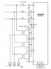
The datasheet, at page 103 has the circuit you need. The voltage input is measured using precision resistors while the currents are measured with current transformers that may be on your PCB for small loads or un the load wires for big loads.
Pay a lot of attention working with this kind of circuits because all your circuit became "live" and you and everything connected to the circuit (PC, development tools, ...) are at big risk, if you don't have enough experience.
The IC maxq3180 is a SPI peripheral that takes analog inputs (current, voltage, ...) and does the correct calculation so that an external microcontroller, using the SPI bus, is able to get and maybe display on an LCD those values. The maxq3180 needs a 3.3V power supply so it's better to use a microcontroller with the same supply ... let's say a PIC18F device with SPI port. The power supply for both the PIC and the MAX should be taken from two phases of the 3-phases line under measurement. You can use a small transformer or a small switching regulator ...
But again ... if you do these questions, it seems you have no experience with live circuits so be very very careful because it's dangerous to test and debug such circuits.
This site uses cookies to help personalise content, tailor your experience and to keep you logged in if you register.
By continuing to use this site, you are consenting to our use of cookies.