Hi
Am new to the forum but reading over peoples posts everyone seems very helpful so i thought i would see if i could get in on the action.
I'm trying to design a contactless power monitor. Planning to use some sort of hall sensor clipped around the mains supply and then use this output to calculate the power being consumed.
I know i could buy one of these for fairly cheap but am trying to 'improve' ( more like get) an understanding of electronics more.
What I am thinking is that I can use a hall sensors ouput (an ac voltage representative to the current flowing through the wire?) and a pic to calculate the power.
I wasn't planning on taking a voltage reading as I assume that this doesn't fluctuate much around 230V (uk) so was just going to use this static value for the calculations.
Anyway my main query is what do i have to do with the ac signal from the hall to get it into the pic. I know i will need to convert it to DC and that some sort of rectification will be needed to do this.
I'm assuming that the currents i will be reading will about 80A and i want to measure fairy accurately from 0A-80A.
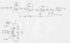
I have been looking around and have found a circuit that says it does something like this but i dont understand it much.
The first 2 sections look like(according to google searches) low pass filters and then some sort of rectifier and voltage follower. As for the other section and the 'float' voltages i have no idea whats going on.
Could anyone give me a clue as to why/what is being filtered and how the rectifier is working? Also any ideas as to other section would be greatly appreciated.
Am new to the forum but reading over peoples posts everyone seems very helpful so i thought i would see if i could get in on the action.
I'm trying to design a contactless power monitor. Planning to use some sort of hall sensor clipped around the mains supply and then use this output to calculate the power being consumed.
I know i could buy one of these for fairly cheap but am trying to 'improve' ( more like get) an understanding of electronics more.
What I am thinking is that I can use a hall sensors ouput (an ac voltage representative to the current flowing through the wire?) and a pic to calculate the power.
I wasn't planning on taking a voltage reading as I assume that this doesn't fluctuate much around 230V (uk) so was just going to use this static value for the calculations.
Anyway my main query is what do i have to do with the ac signal from the hall to get it into the pic. I know i will need to convert it to DC and that some sort of rectification will be needed to do this.
I'm assuming that the currents i will be reading will about 80A and i want to measure fairy accurately from 0A-80A.
I have been looking around and have found a circuit that says it does something like this but i dont understand it much.
The first 2 sections look like(according to google searches) low pass filters and then some sort of rectifier and voltage follower. As for the other section and the 'float' voltages i have no idea whats going on.
Could anyone give me a clue as to why/what is being filtered and how the rectifier is working? Also any ideas as to other section would be greatly appreciated.