Continue to Site

Welcome to our site!

Electro Tech is an online community (with over 170,000 members) who enjoy talking about and building electronic circuits, projects and gadgets. To participate you need to register. Registration is free. Click here to register now.

  • Welcome to our site! Electro Tech is an online community (with over 170,000 members) who enjoy talking about and building electronic circuits, projects and gadgets. To participate you need to register. Registration is free. Click here to register now.

"Power loss" switch

Status
Not open for further replies.
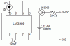
I have a device that's powered by a 5V DC adapter; I would like to set something up so that an LED blinks when power is lost. I already have an LM3909 that will be connected to an AA battery for the blinking circuit, so that's taken care of, I just need a way to turn it on when the 5V power power is lost.

I know I could use a 5V SPDT relay, with the battery wired through the NC contact... but is there anything simpler/more electrically efficient than a relay? I'd like to go solid state if possible.
 
A small PNP transistor should work. Connect the transistor emitter to the battery, the base to your 5V supply through a resistor, and the collector to the LM3909. When the 5V is lost, the base resistor will go to ground, turning on the transistor and energizing the LM3909.

The base resistor should be sized to give adequate base current to saturate the transistor (0.1 times the collector current, or 0.2 times the collector current if you want to maximize efficiency). For one 1.5V battery, the resistor value would then be (1.5V - 0.65V) / (0.1 * collector current). The collector current is whatever the LM3909 draws when powering the LED.
 
Last edited:
I would just have an LED to indicate that the power is normal. The lack of the LED can alert you to the missing power...
Sure as hell, by the time you need it, the battery will have died of old age, even if you are not drawing any power from it...
 
Last edited:
Fantastic -- I figured a transistor might work, but I was just concerned about connecting the dissimilar voltages.

So something like the schematic in the attached image should work?

I chose 22kΩ because the LM3909 datasheet shows the average drain as 0.32mA, or 0.00032mA, and thus (0.85 / (0.1 * 0.00032)) = 26562.5 and (0.85 / (0.2 * 0.00032)) = 13281.25... a 22k resistor is the closest common value available and falls between those two so it seems like a safe bet to me.

Does anyone see any problems with this?

I have yet to receive my LM3909's (they're on their way), so I can't test-wire this at the moment, but I'm just trying to get everything else lined up and ready to go for it.

EDIT: Fixed transistor symbol
 

Attachments

  • lm3909_power_loss_indicator.gif
    lm3909_power_loss_indicator.gif
    2.8 KB · Views: 164
Last edited:
I ordered them through FutureLEC, who has them (albeit at a premium of $2.75ea). I like tinkering with LEDs, and the 3909 is just too useful to not play with once in a while.

I don't know why some China fab plant doesn't pick up the design of the 3909 and make their own knock-offs... they could probably make a killing even off the hobbyist market.
 
You have the emitter and collector reversed on your schematic.
 
*waves his hand*
"there is nothing wrong with this schematic"

;)

Anyways, schematic symbol aside, is that how you were suggesting I use the transistor?
 
Yes, that should work.
 
Status
Not open for further replies.

New Articles From Microcontroller Tips

Back
Top