Continue to Site

Welcome to our site!

Electro Tech is an online community (with over 170,000 members) who enjoy talking about and building electronic circuits, projects and gadgets. To participate you need to register. Registration is free. Click here to register now.

  • Welcome to our site! Electro Tech is an online community (with over 170,000 members) who enjoy talking about and building electronic circuits, projects and gadgets. To participate you need to register. Registration is free. Click here to register now.

power harvesting - electromagnetic induction test rig

Status
Not open for further replies.

kattoju

New Member
hi,
i m trying to build a test rig to demonstrate the amount of current and voltage i am able to generate from vibrations.

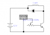
the rig has input and out put reed coils (devoid of the switch) acting as the coil
and a 0.5 tesla magnet which passes through them. the idea is to energise the input coil with an ac supply make the magnet jump to the output coil .thereby inducing an emf in it. the coil has a 400 ohm resistance. the voltage im able to supply to the coil from a signal generator is only a 6 volts . is there any way to amplify the power from the signal generator so i would be able to supply more power to the input so as to make the magnet move faster and more number of times into and out of the output coil to get more power out. i have to test the coil at very low frequencies also say starting from a 5-10 hz or even 20 hz.
 
something like this?
 

Attachments

  • snap1.png
    snap1.png
    2.2 KB · Views: 257
How about a simple mains transformer? A 12 volt wallwart transformer will take your 6 volt input and output 60.
Personally I would physically agitate the magnet by hand or you'll never know what you'll get from a real vibration, use a small electric motor discs and attached levers to give you a reciprocating action. Or better yet expose the setup to the actual vibrations you expect to utilize and measure what you get. By the way, the device is going to be large, expensive (lots of copper wire) and only produce very small amounts of power even if designed well.
 
Last edited:
How about a simple mains transformer? A 12 volt wallwart transformer will take your 6 volt input and output 60.
Personally I would physically agitate the magnet by hand or you'll never know what you'll get from a real vibration, use a small electric motor discs and attached levers to give you a reciprocating action. Or better yet expose the setup to the actual vibrations you expect to utilize and measure what you get. By the way, the device is going to be large, expensive (lots of copper wire) and only produce very small amounts of power even if designed well.

hi sceadwin,

im using a reed coil ( removed the switch) put in a neo mag(5600 guass) that is comfortably moving in the coil. i ve tested it vith a concrete shaker at freq( 10-110 hz).... was able to produce 20 & 50 v peaks every milli second. at 55 hz and 100 hz respectively.... what does that mean.

hi,
Did you try any of the suggestions posted in your other thread on this same topic.??

One post suggested an audio amplifier IC, DC coupled or thru a large capacitor, thats the way I would go.:)
 
hi,
Did you try any of the suggestions posted in your other thread on this same topic.??

One post suggested an audio amplifier IC, DC coupled or thru a large capacitor, thats the way I would go.:)

i will have to check it out ...... but some one suggested i use a signal generator and mosfet switch and supply the coil with 20+ volts .....
 
i will have to check it out ...... but some one suggested i use a signal generator and mosfet switch and supply the coil with 20+ volts .....

hi,
I would guess you dont need the 'drive' coil referenced to 0v.? [ no direct 0V connection]


EDIT:
As you want the drive coil current to change direction so that magnet is push/pulled, you need either a dual supply or a large capacitor in the driving circuit connection.
 
Last edited:
hi,
I would guess you dont need the 'drive' coil referenced to 0v.? [ no direct 0V connection]


EDIT:
As you want the drive coil current to change direction so that magnet is push/pulled, you need either a dual supply or a large capacitor in the driving circuit connection.


hi eric,
a signal generator which produces a square wave(+6v) ,is connected to the gate of the mosfet, the source of the mosfet is connected to 0V, and the drain of the mosfet is connected to one end of the coil. the other end of the coil is connected to a 24 volt supply. is this what yu meant by dual supply?

hi,
Consider this, the drive coil current flows one way and the magnet moves to one end of the drive coil, to get it back the other way the coil current has to change direction.
 
hi,
Consider this, the drive coil current flows one way and the magnet moves to one end of the drive coil, to get it back the other way the coil current has to change direction.
yes. there is another coil2 in to which the magnet moves when coil 1 is energised ( mosfet on). the magnet moving in to coil2 induces current in it. and and when the mosfet is switchd of the magnet comes back in to coil1 .......... the process keeps going on.....
 
yes. there is another coil2 in to which the magnet moves when coil 1 is energised ( mosfet on). the magnet moving in to coil2 induces current in it. and and when the mosfet is switchd of the magnet comes back in to coil1 .......... the process keeps going on.....

I understand your project setup OK.

How is the magnet getting back into the drive coil after its been pushed out, gravity or what.?
 
I understand your project setup OK.

How is the magnet getting back into the drive coil after its been pushed out, gravity or what.?
or i was thinking using springs on either side of the magnet attached to it. and the other ends of the springs attached to the ends of the coils.... so it can be used when it is horizontal...... the spring can bring it back to the input coil ..... or else it has to be gravity if i intend to use it vertically.....
 
yep gravity .....

OK,
So all you need is a unidirectional current pulse thru the drive coil.
So the SG connect to a FET gate as you describe should work, don't forget the clamp diode across the drive coil.

Are you sure gravity will act fast enough to give a 15Hz rate.??
 
OK,
So all you need is a unidirectional current pulse thru the drive coil.
So the SG connect to a FET gate as you describe should work, don't forget the clamp diode across the drive coil.

Are you sure gravity will act fast enough to give a 15Hz rate.??

well i did test it with a sine wave from a signal generator at 20 hz .... coil2 gave me ac voltage of 6 volts ..... thats vat yu mean isnt it?
 
well i did test it with a sine wave from a signal generator at 20 hz .... coil2 gave me ac voltage of 6 volts ..... thats vat yu mean isnt it?

I would build the FET driver and see if it gives the results you expect.
 
I would build the FET driver and see if it gives the results you expect.
the voltage generated in coil2 will be ac voltage.... im using a rectifier to convert to dc ...... and then planing to use a LTC3108 CONVERTER CHIP to bring the voltage down to 3v .... will this work?
 
the voltage generated in coil2 will be ac voltage.... im using a rectifier to convert to dc ...... and then planing to use a LTC3108 CONVERTER CHIP to bring the voltage down to 3v .... will this work?

the datasheet says its a STEP UP device.????
 
Status
Not open for further replies.

Latest threads

Back
Top