Continue to Site

Welcome to our site!

Electro Tech is an online community (with over 170,000 members) who enjoy talking about and building electronic circuits, projects and gadgets. To participate you need to register. Registration is free. Click here to register now.

  • Welcome to our site! Electro Tech is an online community (with over 170,000 members) who enjoy talking about and building electronic circuits, projects and gadgets. To participate you need to register. Registration is free. Click here to register now.

power electronics circuit analysis

Status
Not open for further replies.

ptewright

New Member
Hi,

I'm doing a project based on the following circuit. I really need some help analyzing this circuit!!! I'm not too familiar with power electronics. :(

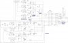
Basically this circuit is suppose to control the operation of solenoids, a pump and a heater from a microprocessor. Here's what I figured out so far. They are controlled from the microprocessor outputs "heater, pump, sol, sol". These outputs enable the triac drivers (u8, u7, u2, u1), if the outputs of the triac drivers are out of phase, the driver is activated which enables the gate of the triac gate. Varistors are placed in parallel to protect the triac from current surges. The RC networks act as snubbers to the triac.
What i don't understand is that shutdown circuit. It's suppose to disable the pump and the heater. They are deactivated when a thermostat is opened or from a command from the microprocessor via "out". If it was deactivated from the thermostats then this circuit lets the microprocessor via "in". How do the components in this circuit makes this happen?

Thank you,
Pete
 

Attachments

  • circuit_420.jpg
    circuit_420.jpg
    107.7 KB · Views: 1,417
Oh, yeah, it works.
I would guess this is some kind of solar panel control circuit. Not all circuitry available is used in this application, as can be seen by the no-connects at J1-5 and J1-9.
Basically, the two SOL lines drive the optocouplers at U8 and U7 to energize the two SCRs at Q9 and Q8, respectively. The varistors and fuses on these two circuits provide overvoltage and overcurrent protection. So, the solenoid valves are connected from AC hot to AC neutral through this arrangement. Simple.

The heater and pump circuits are something else. Once again two inputs, PUMP and HEATER, are used to drive optocoupler-SCR combos to introduce the AC hot to one side of the heater and pump. But, the route back to AC Neutral gets all complicated by the SHUTDOWN circuits.
First, the return (AC neutral) side of the pump and heater are ganged. One or both must be energized, and both THERMOSTAT switches closed, to provide power to the SHUTDOWN circuits. As can be seen, two bridge rectifier/bypass cap combos, which don't need closed thermostat switches, recieve power to produce a low voltage DC to run this circuitry.
As long as the lower DC supply (D2/C9) is running, this will energize and turn on the optocoupler at U9, which in turn biases on the NPN transistor at Q10, which (finally!) puts out a +5V signal on the IN line. I can only think this tells the processor that either, or both, the pump or heater is energized.

The upper SHUTDOWN circuits actually control the AC. They run off the DC supply of D3/C11. While there is a high (+5V?) coming in on the OUT line to bias on the transistor at Q11, and jumpers J1 and J2 are installed, the optocouplers at U6 and U4 are on and energizing the SCRs at Q2 and Q1. BOTH these SCRs have to be on in order to complete the power path from the pump and/or heater to the AC Return.
So, as you said, the thermostat switches or the processor can kill the power.

While it's actually a little more complicated, that's the gist of it.

can someone tell me where the regulated +5V connected to the upper ICs comes from?

Russlk, the pump and heater have three connections because they're AC devices, so have AC hot and neutral and safety ground.
The H11A1s are garden variety optocouplers: drive the LED on to bias the NPN transistor on. Connecting the base on pin 6 to a 5meg resistor to 5V protects it from firing in the noisy AC environment, and gives it a bit of "snap action".
Q10 is your typical garden variety NPN switching transistor.
 
Last edited:
hi
i m final year student of electronics and i like project based on image processing. will u give me any suggesions about this or some image processing projects?
 
hi
i m final year student of electronics and i like project based on image processing. will u give me any suggesions about this or some image processing projects?

I suggest that you not hijack someone else's thread.
 
Status
Not open for further replies.

New Articles From Microcontroller Tips

Back
Top