I have decided to design a new HVAC control system for my house. The main PCB is going to replace the thermostat in the wall in my home. Therefore, I want the 24V coming out of my wall that has been powering my current thermostat to power the new one. I want it to be pretty much plug and play so I have decided to put the relays on the board, much like the guy has done in the following link... MGDEngineering.com - HVACMontior: A stand-alone, web-accessible thermostat.
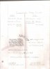
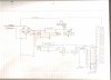
I have been able to connect the devices together, but am not sure about the design of my PCB as far as power distribution. The first attached image is the components going on my PCB and their corresponding voltages and current draws / other applicable information about the parts I have tentatively selected, and the second image is the circuit I have come up with to provide the correct power to all of these devices.
The output of my board is going to be 24V AC controlled by relays. Much similar to the project done by MGD Engineering shown in the link. There needs to be 10 of these relays for my system, and there is a possibility they will all be turned on at the same time.
On the circuit diagram, the two wires coming out of the wall are on the left. I know they need to be full wave rectified by the four diodes (D1 - D4). I have been told (by an A/C guy that I know) that there is usually 40W on the 24VAC hot coming out of the wall. So going with that I figured that P = V*i so plug in numbers 40 = 24*i and find there is 1.67 Amps on this input. This is where my first uncertainty occurs. I currently have the 24V AC line coming up and out (in parallel) from the input to the contact of the relay. I am not sure if this is correct and also not sure how to calculate how much power these will draw in a state where they are all turned "on". I want to calculate this power to make sure there will be enough power left to run my other PCB components. I am fairly sure 40W is plenty, seeing as most of my devices run in the mW range but I would like to be sure before sending the PCB out for fab. Also, at some point, none of the relays will be turned "on" so I want to make sure the diodes in the bridge can handle the 1.67A.
Next problem is the smoothing capacitor (C1 in the circuit). I have read a lot about AC to DC conversion and understand the point of the smoothing capacitor, but have not been able to find a way to calculate the value that I need for this part.
I think I have found applicable voltage regulators and was able to get values for C2, C3, C4, and C5 from data sheets.
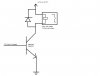
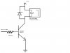
Onto the output. The microcontroller I am using has I/O pins that output 4mA at 3.3V. I have read about this as well and think that using a Darlington array is the way to go. The relays I have found have a coil voltage of 3V, coil current of 73.3 mA, and coil resistance of 40Ω. I have the common of the ULN2803 Darlington array connected to my 3.3V regulator output, but I am thinking I might need at least 1 more of these regulators because they only output 800 mA. I have one side of the coil connected to the corresponding output of the ULN2803 and the other side connected to the 3.3V source (I only drew the connections on a few because I did not want the drawing to get sloppy). I am not sure if these connections are correct.
This is my first attempt at an electronics project and I am enjoying doing it, just a little stumped on this power distribution. I have done serious searching on the internet but and stumped and have turned to this forum as a last resort, as I have read other useful information here. Thank you in advance for any assistance!
I have been able to connect the devices together, but am not sure about the design of my PCB as far as power distribution. The first attached image is the components going on my PCB and their corresponding voltages and current draws / other applicable information about the parts I have tentatively selected, and the second image is the circuit I have come up with to provide the correct power to all of these devices.
The output of my board is going to be 24V AC controlled by relays. Much similar to the project done by MGD Engineering shown in the link. There needs to be 10 of these relays for my system, and there is a possibility they will all be turned on at the same time.
On the circuit diagram, the two wires coming out of the wall are on the left. I know they need to be full wave rectified by the four diodes (D1 - D4). I have been told (by an A/C guy that I know) that there is usually 40W on the 24VAC hot coming out of the wall. So going with that I figured that P = V*i so plug in numbers 40 = 24*i and find there is 1.67 Amps on this input. This is where my first uncertainty occurs. I currently have the 24V AC line coming up and out (in parallel) from the input to the contact of the relay. I am not sure if this is correct and also not sure how to calculate how much power these will draw in a state where they are all turned "on". I want to calculate this power to make sure there will be enough power left to run my other PCB components. I am fairly sure 40W is plenty, seeing as most of my devices run in the mW range but I would like to be sure before sending the PCB out for fab. Also, at some point, none of the relays will be turned "on" so I want to make sure the diodes in the bridge can handle the 1.67A.
Next problem is the smoothing capacitor (C1 in the circuit). I have read a lot about AC to DC conversion and understand the point of the smoothing capacitor, but have not been able to find a way to calculate the value that I need for this part.
I think I have found applicable voltage regulators and was able to get values for C2, C3, C4, and C5 from data sheets.
Onto the output. The microcontroller I am using has I/O pins that output 4mA at 3.3V. I have read about this as well and think that using a Darlington array is the way to go. The relays I have found have a coil voltage of 3V, coil current of 73.3 mA, and coil resistance of 40Ω. I have the common of the ULN2803 Darlington array connected to my 3.3V regulator output, but I am thinking I might need at least 1 more of these regulators because they only output 800 mA. I have one side of the coil connected to the corresponding output of the ULN2803 and the other side connected to the 3.3V source (I only drew the connections on a few because I did not want the drawing to get sloppy). I am not sure if these connections are correct.
This is my first attempt at an electronics project and I am enjoying doing it, just a little stumped on this power distribution. I have done serious searching on the internet but and stumped and have turned to this forum as a last resort, as I have read other useful information here. Thank you in advance for any assistance!