Continue to Site

Welcome to our site!

Electro Tech is an online community (with over 170,000 members) who enjoy talking about and building electronic circuits, projects and gadgets. To participate you need to register. Registration is free. Click here to register now.

  • Welcome to our site! Electro Tech is an online community (with over 170,000 members) who enjoy talking about and building electronic circuits, projects and gadgets. To participate you need to register. Registration is free. Click here to register now.

Power darlington module motor driver

Status
Not open for further replies.
Hi there,

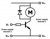
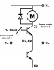
I was wondering if anyone could try to explain to me, why the Vcc in my circuit is not doing anything here. Whatever voltage I use, the only thing changing the motor voltage drop is the base voltage. Why doesn't the transistor module not work as regular darlingtons (controlling current through collector-emitter as a function of the applied base current). I'm using transistor modules MG100G2YL1, but I can unfortunately only find a datasheet for an equivalent component. That may however not be the main problem. The important data are around

hFE = 100-200
VCEsat = 2.5 V
VEBO = 7 V

The attached circuit test uses only a single transistor of the half-bridge component. I'm using a dual channel power supply, and as long as the Vcc/Vss cables are connected to channel 1 the motor runs, no matter the voltage. Can anyone help?
 

Attachments

  • circuit.png
    circuit.png
    25.2 KB · Views: 152
Hello,

So you are saying that you are using an unknown transistor bridge, only one part of it?
Do you have an ohm meter or another single transistor that can handle the power?
 
This is the datasheet.

The module is a dual, can you post the complete circuit showing how all the pins are connected.
 

Attachments

  • datasheet.pdf
    299.7 KB · Views: 170
@MrAl: I know it is not optimal to use an unknown transistor module, but that was what I had, and wanted to see if it could do the job

@ericgibbs: I actually have that datasheet, but it only includes the MG100H2YL1, but it seems very similar. What more circuit schematic are you seeking? I have updated the schematic, but there is no more circuit for now, as I just wanted to test the transistor module, which I assume is possible with the given circuit, right?
 

Attachments

  • circuit2.png
    circuit2.png
    33.2 KB · Views: 159
Hi again,

Your G2 unit is similar to the other G2 units on the data sheet Eric posted except for maybe the gain. There are only two transistors (diagram 1) not three, which means less gain (like 80 to 100 or around there). By comparison, the H2 unit has three transistors and higher gain (like 200) but the G2 unit only has 2 transistors.
It looks like the pinout is the same for all of them though right? You could do some simple tests to make sure you have the right pinout anyway.

If you cant resolve this issue with the data sheet then maybe something is really wrong like a blown part or something else like bad connections. Are you sure you have the right part number? Can you test it with a small power supply or battery and a resistor to drive the base?
Also, does the package you have look like the data sheet drawing? Did you buy the part from a catalog?
 
Last edited:
Thanks for the reply MrAl

It is no big deal, that it has that lower gain, and all I want is to use the component as a switch with e.g. PWM. The component is not from a catalog, but from an old robotics controller, but the part number is written clearly on the side of it, so I'm sure about that. Actually this small test was designed to test whether or not the component works as it should. I apply a base signal of 7 V and 4 mA to 25 mA, which provides a voltage drop across the load (resistor or motor).

The problem is though, that the power supply to the load does not seam to be used. A higher base current also does not change the voltage drop across the load, which is stead at 4.4-4.5 V no matter all other power supply voltages (of course the voltage is decreasing, when the base power supply is below 4.4 V. So maybe the component is broken
 
Hi again,

What is your Vcc supply voltage?
If you are saying that the voltage across the load decreases when you drop the base voltage of the transistor then that is good. That's the way it should work.
Remember however that with the darlington setup you may see a relatively high drop across the transistor itself. It could be as high as 2.5v, although i would think 2v
would be more typical.
 
Status
Not open for further replies.

Latest threads

New Articles From Microcontroller Tips

Back
Top