Continue to Site

Welcome to our site!

Electro Tech is an online community (with over 170,000 members) who enjoy talking about and building electronic circuits, projects and gadgets. To participate you need to register. Registration is free. Click here to register now.

  • Welcome to our site! Electro Tech is an online community (with over 170,000 members) who enjoy talking about and building electronic circuits, projects and gadgets. To participate you need to register. Registration is free. Click here to register now.

Power Amplifier Output Distorting

Status
Not open for further replies.

stobbz

New Member
Hello folks,

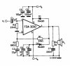
As part of a larger project, I've constructed a TDA2030H power amplifier. As part of the characterisation of the amplifier, I decided to test its frequency response with respect to current output.

The only alteration I have made to the circuit was to replace a 100k gain control resistor with a 500k potentiometer. With that potentiometer set to its lowest value, hence providing low gain, I went to measure the amplifier output current over a range of frequencies.

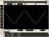
As expected, I recorded a steady constant level of output over a range of frequencies. However, when I reached 100 kHz, the output (Green trace in the picture) started to distort. At 60 kHz, the output started to decrease slightly, so it would be expected that the output would continue to decrease with increases in frequency. However, at 100 kHz, it distorts and begins to rise again.

Any idea why this is happening or how I could test the frequency response?
 

Attachments

  • Amplifier distorted output at 100khz.jpg
    Amplifier distorted output at 100khz.jpg
    196.9 KB · Views: 162
The only alteration I have made to the circuit was to replace a 100k gain control resistor with a 500k potentiometer. With that potentiometer set to its lowest value, hence providing low gain, I went to measure the amplifier output current over a range of frequencies.

when I reached 100 kHz, the output (Green trace in the picture) started to distort. At 60 kHz, the output started to decrease slightly, so it would be expected that the output would continue to decrease with increases in frequency. However, at 100 kHz, it distorts and begins to rise again.

A good 100khz is asking too much. The part placement is critical.
What 100k gain resistor? If you added a pot around the amplifier to adjust the gain the long leads are not good.
If you attenuated the input that is the way it is done. If you changed the resistance form output to input, the amplifier was never designed for low gain in this mode.
 
Sorry, the circuit shown there comes straight from the data sheet, released in 1993. The amplifier is sold as a self assembly PCB, were some of the component values vary from the circuit given in the datasheet. I should have mentioned this. The 100k resistor is given in place of the 22k (R1) in the diagram.

I believe the bandwidth of the amplifier is 140kHz, could I just approaching that limit? Thanks for the advice, really helpful.
 
Often the gain pot is on Vi.
I have not read the data sheet lately but I don't think it was not designed to operate with R1 near 0 ohms.
Normally distortion is real bad at the bandwidth limit. (or near the limit).
It is hard to find distortion specs above 20khz on many audio amplifiers. (also below 20hz)
 
"I believe the bandwidth of the amplifier is 140kHz"

On an Audio power amplifier? Highly unlikely and unnecessary. 20 Khz maximum and already with reduced performance

I read the data sheet. On figure 9 there is a plot of distortion vs frequency, and distortion rises above 10 Khz and stops being plotted at 15 Khz.
 
Perhaps the power supply is struggling to provide current when it is operating at 100KHz. If you are using a switching supply, perhaps that distortion is at the frequency of the switching regulator?
 
Perhaps the power supply is struggling to provide current when it is operating at 100KHz. If you are using a switching supply, perhaps that distortion is at the frequency of the switching regulator?

That's a reasonable theory, especially for the negative power supply. If possible, maybe OP could try swapping the positive and negative power supplies to see if the distortion moves to the upper half of the waveform.
 
"I believe the bandwidth of the amplifier is 140kHz"

On an Audio power amplifier? Highly unlikely and unnecessary. 20 Khz maximum and already with reduced performance

I read the data sheet. On figure 9 there is a plot of distortion vs frequency, and distortion rises above 10 Khz and stops being plotted at 15 Khz.

I agree - the whole thread seems pretty pointless, complaining that an audio amplifier wont work as an RF amplifier?.

Audio is 20Hz to 20KHz, no need (or point) checking it out of those design limits - I would also suggest NOT altering the feedback resistor value. The OP though hasn't posted his circuit (as he was asked to), but merely a partial one from the datasheet - hopefully the real circuit includes a few more capacitors for HF rolloff?.
 
That 100Khz is Getting pretty High in Frequency for this chip.

However, Did you Breadboard this, or Make a PCB For it?

On these types of Integrated Amplifiers, It is Important to use a "Common Point Ground".
Not a Buss type Ground.

A Buss type Ground can result in Ground Loops, Causing Distortions.

A Common Point Ground Might Help!
 
From data sheet: "1. Closed loop gain must be higher than 24 dB".
As I have mentioned before, setting the gain to 1 is not good. It was never designed to operate in that mode. I am surprised it does not oscillate at 500khz in this mode. I can see it wants to oscillate at 300k.
 
Thanks for all the replies, there is plenty here for me to consider and try. Also, I appreciate the comments on the 20 Hz to 20 kHz range, after all, that's the range of human hearing so why would an audio amplifier operate above 20 kHz?

However, I was asked to show the amplifiers frequency response, so I was looking for that typical DC response over a certain range of frequencies (which I got), but then was hoping to see the output gradually reduce with further increases in frequency, as you would expect. If it's distorting because that's just an unreasonable frequency for it to operate at, that's fine, but the intention of this thread was to find out if there could be any other reasons for the distorted output and if I could actually observe the frequency response.

Again, thanks for all the replies, your experience has been helpful! :D
 
Thanks for all the replies, there is plenty here for me to consider and try. Also, I appreciate the comments on the 20 Hz to 20 kHz range, after all, that's the range of human hearing so why would an audio amplifier operate above 20 kHz?

Even though the Hearing range is 20 to 20,000, A good amplifier will work to Higher Frequencies to Reproduce the upper Harmonics.
This helps the sound to sound more Realistic to the Listener.
And even 50 Khz Should be Plenty high enough.
 
I built a board with a switcher at 25KHz, which I could almost sorta kinda hear... but every time I had it running and my son came over he would walk right up to it and turn it off... he could hear it real good, and it bothered him...
 
It is VERY RARE for a person to hear that High of a Frequency.
You Might actually Check it with a Scope or Frequency Counter?

Or Possibly your just hearing the Lower Harmonics?
 
I built a board with a switcher at 25KHz, which I could almost sorta kinda hear... but every time I had it running and my son came over he would walk right up to it and turn it off... he could hear it real good, and it bothered him...
When I was a teenager I heard "ultrasonic" motion detectors in concert halls and muzeums. They were at an extremely high frequency and were very loud. Now I am 67 and I can still hear most harmonics in music and the 15,750Hz from the horizontal transformer in an old CRT TV.
 
not that rare for young people, and I used a scope to syncronize the frequency in. It was being driven by a microprocessor, so I'm not sure there were any lower harmonics???

5usec / div
 

Attachments

  • 2005 04 20 008.jpg
    2005 04 20 008.jpg
    432.7 KB · Views: 119
Last edited:
Status
Not open for further replies.

Latest threads

New Articles From Microcontroller Tips

Back
Top