First of all big thanks to audioguru who helped me out with an previous amp design. Sadly i couldn't use it because transformer has just too big dynamic resistance.
I researched and worked on my own and i came up with an alternative design. I managed to get everything working properly but just need to modify one last thing.
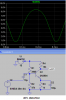
I need to do a 180 degrees phase shift of signal before the base of the
transistor Q14. After that just trim the voltage gain a bit and I'm done.
I need help with that phase shifting. I already tried using various combinations in a place of the lover Darlington pair without any success. I tried compound pair and various combinations of transistors npn and pnp with and without resistors.
I thought of using an OP amp to do the phase shift, but thats a really lame solution.


I researched and worked on my own and i came up with an alternative design. I managed to get everything working properly but just need to modify one last thing.
I need to do a 180 degrees phase shift of signal before the base of the
transistor Q14. After that just trim the voltage gain a bit and I'm done.
I need help with that phase shifting. I already tried using various combinations in a place of the lover Darlington pair without any success. I tried compound pair and various combinations of transistors npn and pnp with and without resistors.
I thought of using an OP amp to do the phase shift, but thats a really lame solution.