Continue to Site

Welcome to our site!

Electro Tech is an online community (with over 170,000 members) who enjoy talking about and building electronic circuits, projects and gadgets. To participate you need to register. Registration is free. Click here to register now.

  • Welcome to our site! Electro Tech is an online community (with over 170,000 members) who enjoy talking about and building electronic circuits, projects and gadgets. To participate you need to register. Registration is free. Click here to register now.

Power a subwoofer from a remote speaker.

Status
Not open for further replies.

mramos1

Active Member
My sons car has speakers in the rear I can get to from the trunk and 12V and GND, but NO ingnition (turn on) wire.

We have a powered (AMP) sub-woofer tube to add to the trunk now.

The plan is to tap a speaker in the rear/trunk with no major load to the speaker we tap, with a circuit, and power a relay to turn on the power to the subwoofer amp.

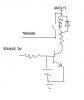
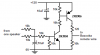
I need ideas. Tap a speaker, see if there is AC/audio. I was thinking a 1:1 transformer to a power transistor to the relay coil. Maybe an opto-isolator..

Anyone have a design or ideas. I have not put a meter on the speaker to see if a DC offset is there with the radio on or looked to see what the audio levels are.

Looking for simple. I have TIP 30/31/32 and 6 amp N/P channel FETs..
 
The ordinary speakers in a car are not designed to be sub-woofers, so maybe the low frequencies are not delivered to them. Try it, it might work if the sub-woofer's amp has a bass boost control.

Most car radios have a bridged amplifier that applies signal to both wires of each speaker, causing the DC of each wire to be about 7V when the radio is turned on. Connect a resistor to a speaker wire then a capacitor to ground as a filter then the base of a transistor that can give indication to the sub-woofer's amp turn on wire.
 
Audioguro. Will try that tonight. Can not get any simpler than that..

speaker* to resistor to cap_ground/base_transistor_NPN I take it. And emitter to ground and add coil/diode/resistor on collector to 12V?
 
Last edited:
I can't remember if the "turn on" wire of an amplifier needs to be grounded or positive to turn on an amplifier. A single transistor with a resistor from its collector to the positive supply will provide a ground output when it is turned on, add a second transistor circuit to it for a positive output.
 
Audioguru, it is positive. I drew it out tonight, if I am no buried in works I will hook it all up tomorrow. listen for a relay click, all good, hook it all up. Starting with a 15K resistor to be safe. On the cap, 100uF to start, will see what I get heat wise :)

Thanks for the help.

Otherwise, I would have a 16F683 ADC looking and driving it. hahahaha.
And need a regulator, etc..

First try is speaker + to a 15K and 100uF to ground, tap them to the base of a TIP ??? (will look them up in the morning). Emmiter to GND and collertor to coil with diode and a 100 ohm (5 watt plus) to battery. And check voltages and go from there.
 
Does your sub-woofer amplifier need a relay or something to apply power to it? Most car amplifiers have a single low-current wire that is controlled by the car radio to activate the sub-woofer amplifier. It either goes to ground or goes to a positive voltage for the amplifier to turn on.

It sounds like you want to turn on your sub-woofer amplifier with a relay that applies 12V at high current to its power supply terminals.
 
AudioGuru.

Right. His car has in the trunk, 2 rear speakers from the radio, also 12 volts and ground. But no ignition wire. Normally I guess they have a wire to tell when the key is on to power the unit up.

Plan was to tap a speaker and if the radio was on (checking via the speaker to a curcuit), power the unit (a Bazooka A200 sub woofer with and amp) with a relay. It is a common or negative ground system on both.

The book shows 12V, GND and ignition, ignition is a +12V to trigger the unit.
 
If the amplifier has a low current trigger wire then a relay is not necessary.
If a rear speaker is driven bridged then both wires have signal and if two resistors add them then the signal will nearly cancel, which makes filtering easy. Then a two-transistors DC amplifier is needed to amplify the 6VDC to 12VDC to feed the trigger wire.
 
Audioguru,

Can you paint scetch the configuration on the 2 resistor 2 transistor idea, value not critical (unless you want to drop them in). And I can cross reference your transistors to the US ones.

I was going to tap one side of one speaker, then work with that. Something like attached.
 

Attachments

  • new7.jpg
    new7.jpg
    8.6 KB · Views: 584
What is the transistor and relay for?
The owners Manual for the Bazooka A200 shows 10 different models. Most have an orange wire terminal labelled "remote". The instructions say to connect it to the radio's antenna power wire or to the car's accessory power terminal so that it gets +12V when you want the Bazooka to be on.

I sketched a circuit to take the 6V from an existing speaker and make +12V from it. Any little NPN and PNP transistors will work. Even Canadian ones.:D
 

Attachments

  • car amplifier remote turn on.PNG
    car amplifier remote turn on.PNG
    8.3 KB · Views: 771
Never thought about the antenna, but I think the power will die once it is up, maybe not. I like the circuit idea better though. And all standard parts. Will build it now.. Thanks ag

And the transistors you picked are the kind we use, I figure BC### type you would be using :)
 
I am in Canada with America a stone's throw distance away (the other side of Lake Ontario). My first job was with Philips where I used a lot of BC### transistors but they are difficult to get here now.
 
Last edited:
I did a schematic capture from you design, did SS PCB, etched/drilled it all in about an hour, my son was all excited. Then people from all over the neightborhood started popping over (3 groups) over a period of hours. So I will stuff and solder it today.

Hope it flys, I think this is a lot nicer than tapping a wire for the antenna.

The thought of pulling the carpet, cutting insullation, splicing, etc.. Thanks in advance.

I worked for Mitel, think they are still around up in Kanata. 15 years, great company. Worked in R&D (D&D back then) in Boca Raton, Florida.. But flew back and forth.
 
Took over and hour to get it working. Eagle defaults are too thin of a trace. I normally bump it up one size. This time I did not. Mistake. I patched it up with some wirewrap..

Works great.. Might thicken the traces and add large pads for the big car wires so if I have to so this again it will not be such a pain. Board was about 1.5x1.5 inches...

It works like a champ. And looks like a small current draw when not running.
 
I am glad to hear that it works well. When the radio is turned off then the transistors are also turned off and don't draw any current.
 
Took over and hour to get it working. Eagle defaults are too thin of a trace. I normally bump it up one size. This time I did not. Mistake. I patched it up with some wirewrap..

Works great.. Might thicken the traces and add large pads for the big car wires so if I have to so this again it will not be such a pain. Board was about 1.5x1.5 inches...

It works like a champ. And looks like a small current draw when not running.

I know this is an old post but it is relevant to an issue I am having now with my Bazooka tube amp/sub install. Do you mind posting the exact circuit you built that worked and if you have had any issues since?

Thank you.
 
Status
Not open for further replies.

New Articles From Microcontroller Tips

Back
Top