Continue to Site

Welcome to our site!

Electro Tech is an online community (with over 170,000 members) who enjoy talking about and building electronic circuits, projects and gadgets. To participate you need to register. Registration is free. Click here to register now.

  • Welcome to our site! Electro Tech is an online community (with over 170,000 members) who enjoy talking about and building electronic circuits, projects and gadgets. To participate you need to register. Registration is free. Click here to register now.

Potentiometer and Transistors

Status
Not open for further replies.

painstream

New Member
Having trouble wrapping my head around this..

So lets say we have two voltage sources, and a dc fan, and we want a user to control the fan speed manually. Lets say one voltage source is coming from a micro controller and the other in independent.

Voltage Sources: 12v and 5v

First of all we do not want the fan to drop before its rated stall current of 5 volts and we want it to use a max rated voltage 12 volt.

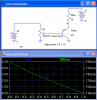
We are using a pot to control the current to a npn transistor. Attached is a working schematic that does exactly what we want. I'm having trouble understanding the math involved with the voltage divider on the 5v side. Calculating the pot is confusing me. If I put a 10k pot the fan will not start until I turn the pot a bit(current is to low) to the base of the transistor. Can someone help me explain the math?

fan_controller_schem.jpg
 
You have to put resistor between pot and transistor.
Current trough the pot should be 10 times larger than base current and, base current should be 20 times smaller than motor current.

Maybe you should use Darlington.

Currently on the left side you don't have a voltage divider because base-emitter junction is acting like a diode.
 
Last edited:
Ahh that makes sense. I think you are correct in I should probably be using Darlington, beta x beta would boost the gain of the low current being applied. Well time to tinker some more :)
 
Ahh that makes sense. I think you are correct in I should probably be using Darlington, beta x beta would boost the gain of the low current being applied. Well time to tinker some more :)
You're on the wrong track with that circuit. You need a PNP emitter follower. The transistor will get a little hot, but it won't hurt it.
Can you cool it with the fan?
 

Attachments

  • fan controller.png
    fan controller.png
    15.1 KB · Views: 415
Why a PNP emitter follower? NPN seems to be a lot more common configuration. Also what is wrong with the Darlington pair, the only downfall I see with this is the increased voltage drop between the junctions but would let me use a much smaller base current to drive the load. At this point i'm trying to figure out how to prevent the fan from reaching stall. If you turn the pot in (off position we will call it) I don't want the fan to turn off but run just above its rated stall voltage. So if you were to turn the fan off it would also start up at that speed without having to turn the dial up and then down again to get past the stall.
 
If this is a real circuit then use PWM. If it's just an exercise we can continue.

PWM (changing the duty cycle) nearly avoids the stall problem. Velleman has a PWM controller kit which I have used for about $30. Jameco has it. RPM sensors in the fan, when incorporated, can totally eliminate the stall problem.
 
Hi,

You can connect this as a voltage follower by simply moving the load to the emitter circuit. The load is the motor plus diode for protection. Leave the battery where it is in the collector circuit.

As others have pointed out, the transistor might get hot if the motor draws significant current. To overcome this problem you could use a heat sink, but the modern approach is to use a pulse width modulation (PWM) scheme. This is where you turn the transistor fully on or fully off for given amounts of time which results in less power getting to the motor which of course reduces it's speed.

The reason PWM works better than the linear approach (the circuit as it is now) is that the transistor is turned either on or off, but not anywhere in between, and this means the transistor never has current and voltage at the same time, but only either one at different times. Since power requires both current and voltage, little power ends up being dissipated in the transistor.
In the linear mode, the transistor often has both current and voltage across it and so there is lots of power being lost and it is lost as heat and that can burn up the transistor or at least waste power.

To get simple PWM perhaps you can use a 555 timer IC chip. Im sure someone here can point you to a simple circuit that varies the duty cycle of the output pulses using a potentiometer as you want to do.
 
Hi,

You can connect this as a voltage follower by simply moving the load to the emitter circuit. The load is the motor plus diode for protection. Leave the battery where it is in the collector circuit.
He wants to get nearly 12V across the motor when the pot is at one end. With an NPN emitter follower, he will get no more than 4.3V. The motor will never start.

Painstream, with the circuit you have (changing the NPN to a Darlington, or not) will give you very nonlinear response to the pot. I showed you the plot of voltage vs pot position for the PNP circuit. The minimum motor voltage is (12-5.7)=6.3V. The maximum is 11.3V.

I considered suggesting PWM, but I guessed that you didn't want something so complex.
 
Can you imagine a wheelchair with a linear circuit controlling the speed of the motor?
Turn it up a bit, it doesn't start rolling.
Turn it up more and it is still stalled and doesn't start rolling.
Turn it up more and it goes like a ROCKET!

Then try to slow down. The motor instantly stalls and throws the person over the handlebars.

Of course wheelchairs use PWM to control the speed of the motor while keeping the torque high to avoid stalling.
 
He wants to get nearly 12V across the motor when the pot is at one end. With an NPN emitter follower, he will get no more than 4.3V. The motor will never start.

Painstream, with the circuit you have (changing the NPN to a Darlington, or not) will give you very nonlinear response to the pot. I showed you the plot of voltage vs pot position for the PNP circuit. The minimum motor voltage is (12-5.7)=6.3V. The maximum is 11.3V.

I considered suggesting PWM, but I guessed that you didn't want something so complex.


Hi,

OH ok well i was assuming that other changes would follow in order to run the thing properly.
A two transistor circuit would do it, and we just talked about that in this forum last week.
 
Can you imagine a wheelchair with a linear circuit controlling the speed of the motor?
Turn it up a bit, it doesn't start rolling.
Turn it up more and it is still stalled and doesn't start rolling.
Turn it up more and it goes like a ROCKET!

Then try to slow down. The motor instantly stalls and throws the person over the handlebars.

Of course wheelchairs use PWM to control the speed of the motor while keeping the torque high to avoid stalling.
I could be wrong, but I think that a wheel chair requires a lot of torque to get it rolling. I wouldn't think a fan would require much torque to get it started.
 
Thanks for the reply guys. I was playing around with an atmega chip today. Reading the analog pot signal and outputting digital PWN to vary the speed of the fan. I got bored and used two thermal resistors, attached one to the intake and one to the outtake to monitor temps and had the microcontroller log this information along with RPMS to an SD card (no idea why, but the data was neat nevertheless) now all I need is a RTC to put a timestamp ha.. I really have no purpose for my project at the moment just dabbling with electronics and trying to gain a better understanding of how things work and what the better way of doing things are.
 
Hi,

Sounds interesting now :)

As you are finding out, the uC is a good way to go about doing these things in this day and age. Once i started using uC chips i cant figure out how i did so well without them for so long. But i know how, with lots and lots of chips and transistors and whatnot instead of one little chip to do everything, and when i say everything i mean EVERYTHING :)

Case in point:
A long time ago i made a frequency counter for my own personal use. It has 8 digits (7 segment LEDs). The chip count came up to something like 24 discrete LS TTL chips! Today we can do almost the same thing with a single microcontroller, although we might still need a driver for the LED display.
 
Status
Not open for further replies.

Latest threads

New Articles From Microcontroller Tips

Back
Top