haxan
New Member
Hi i am using PIC18F4520 and using C18 compiler. I am having problem with my PORTB voltage level.
When i use:
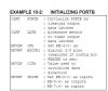
TRISB = 0xF0;
PORTB = 0x00;
I get voltage 1.32 on pins [RB0-RB3] and 0.32 on pins [RB4-RB7]
Should this be happening ? I want either 5v or 0v.
Also could this be due to some weak pull up or anything ?
I want to add a keypad on this port so the RB7-RB4 are input pins.
One more question, which is better to use LAT or PORT while manipulating with pins on microcontroller?
When i use:
TRISB = 0xF0;
PORTB = 0x00;
I get voltage 1.32 on pins [RB0-RB3] and 0.32 on pins [RB4-RB7]
Should this be happening ? I want either 5v or 0v.
Also could this be due to some weak pull up or anything ?
I want to add a keypad on this port so the RB7-RB4 are input pins.
One more question, which is better to use LAT or PORT while manipulating with pins on microcontroller?