wuchy143
Member
Hi All,
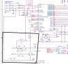
I'm trying to make sense of a POR circuit that is used in a reference design for the TUSB2046(TI USB hub). I attached it and the POR part is in the black box.
My thoughts: From the Datasheet for this part it states that TI recommends a minimum of 100uS to a max of 1ms of reset timing. Looking at the POR circuit that they use in their reference design the RC that they are using is 22 ohms X .1uF = 2.2uS. Clearly this isn't enough. Looking at the NPN transistor upon power up Vbus is asserted before the 3.3V is created from the regulator(the regulator gets it's power from the USB bus a.k.a Vbus) I'm guessing that the transistor will turn on after the hub chip comes out of reset to tell the outside world that it's a full speed device.(pull D+ high with a strong 1.5k pullup) Perhaps that is how they are getting the device to come up correctly(not loosing it's mind and enumerating properly) and not saying "hello world I"m full speed USB" until the device's voltage is stable at 3.3v.
Does anyone have any experience with this chip...or have a better understanding of what TI is doing with their POR circuit? Thanks for the help!
Attachments
Last edited:
