Electro Tech is an online community (with over 170,000 members) who enjoy talking about and building electronic circuits, projects and gadgets. To participate you need to register. Registration is free. Click here to register now.
Welcome to our site! Electro Tech is an online community (with over 170,000 members) who enjoy talking about and building electronic circuits, projects and gadgets. To participate you need to register. Registration is free. Click here to register now.
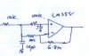
If the circuit is operating from a single 5 volt supply, it won't work due to offset. If it is operating from +- 12 volt supplies, the output will have 21 volts offset in the worst case. Here is how it is computed: 7 mV input offset multiplied by the gain of 680 = 4.76 volts output offset. 0.25 uA bias current multiplied by the 100K input resistor = 0.025 volts input voltage; multiplied by the gain of 680 = 17 volts output offset. Add this to the 4.76 volts = 21.76 volts offset. I neglected the current through the 6.8 meg, so the result is only approximate.
If you use the LT1006 it could work because the offset voltage is 50 uV max and the bias current is 0.5 nA max.
This site uses cookies to help personalise content, tailor your experience and to keep you logged in if you register.
By continuing to use this site, you are consenting to our use of cookies.