Electro Tech is an online community (with over 170,000 members) who enjoy talking about and building electronic circuits, projects and gadgets. To participate you need to register. Registration is free. Click here to register now.
Welcome to our site! Electro Tech is an online community (with over 170,000 members) who enjoy talking about and building electronic circuits, projects and gadgets. To participate you need to register. Registration is free. Click here to register now.
Do you have the detailed circuit or the document from where you got the circuit ?
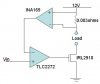
If you just loook at the circuit can be explained as follows
INA169 actually is an amplifier for the voltage drop across shunt resistor (0.003 ohms) but the gain of the INA169 depends on the load resistor (resistor between output of INA169 and GND) but as there is none in the circuit I assume the INA169 is used only to detect the current and not measure it. Meaning that when there is current through shunt resistor (.003 ohms) the output of the INA169 will be high and when there is no current it will be low.
Now this output is fed to opamp TLC2272 (which is a rail to rail opamp) which again seems to be configured in open loop (as there are no resistors to adjust the gain of opmap) so its output will be high when Vin is more than output of INA169 and will be low in reverse case (assuming its negative rail is connected to Ground).
then there is IRL2910 which is a mosfet and it will turn ON when the output of opamp is high and OFF in case of low opamp output
Consider Vin = 0V, and no current through load so ouput of INA169 is low
both the inputs to opamp are low so its output will be low and the MOSFET will be OFF so no current through load
Now consider Vin is certain voltage greater than 0 and less than INA169 high level, as there is no current intially output of INA169 is 0V so the OPAMP outout will go to high level turning on the MOSFET which will allow the current to flow through load and 0.003 ohm resistor. When current flows there will be drop across shunt resistor which will make the output
of INA169 HIGH, now the voltage at -ve terminal is more than +ve terminal, so opamp output switches to low level and turns off the MOSFET, i.e. no load current thus no drop across 0.003 ohm that is low INA169 output and which brings the circuit to intial condition
and the process repeats
The application of the circuit can be understood better if more details about circuit are available
Hmm i'm doing a project right now on a micropprocessor based 4channel light intensity controller. I got the circuit from my lecturer and this is the only part which i don't understand. Anyway thankz for the help :lol:
This site uses cookies to help personalise content, tailor your experience and to keep you logged in if you register.
By continuing to use this site, you are consenting to our use of cookies.