Continue to Site

Welcome to our site!

Electro Tech is an online community (with over 170,000 members) who enjoy talking about and building electronic circuits, projects and gadgets. To participate you need to register. Registration is free. Click here to register now.

  • Welcome to our site! Electro Tech is an online community (with over 170,000 members) who enjoy talking about and building electronic circuits, projects and gadgets. To participate you need to register. Registration is free. Click here to register now.

Pls help on Schmitt trigger op amp cct

Status
Not open for further replies.

math05lumingu

New Member
I want to build a Solar Collector Sun Tracking system, designed by Richard Gideon;

-http://www.phoenixnavigation.com/ptbc/articles/ptbc55.htm


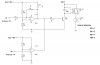
1. How is the operation of IC1d, when its output is connected to the output of IC1b? (**broken link removed**)
2. Also how do i determine/calculate the value of R3, R4, R5 & R6?
 

Attachments

  • ask.jpg
    ask.jpg
    35.6 KB · Views: 632
The circuit does not use an opamp. It uses half a quad LM339 comparator that has open-collector outputs so that the ouputs can be connected together as an OR gate.

The resistor values are determined by how much gain and hysteresis you need.
 
Both comparator sections in the same package cannot have the same pin numbers. You might want to post the relay coil resistance.

R5 + R6 must source enough current from the 9v to saturate Q1, and this depends on the coil current. Figure out these resistors first.

For R3 & R4, 20 mV of hysteresis should be enough.

BTW, the 1N4004 across the coil is supposed to be a signal diode, f'rinstance like a 1N4148 or a 1N914, that can turn on fast and withstand the coil current briefly. The 4004 turn-on risetime is way slow, like for power line freqs.

Use a single point ground, otherwise the lamp current will modulate the ground voltage and you might make yourself a 100 Hz oscillator.

The comparator needs a bypass capacitor across it from + to -.
 
Last edited:
I also thought the same but then the low base-emitter voltage of the transistor will destroy the hysteresis.

Great minds think alike!
Oh, yeah!
:p
 
Last edited:
The circuit does not use an opamp. It uses half a quad LM339 comparator that has open-collector outputs so that the ouputs can be connected together as an OR gate.

The resistor values are determined by how much gain and hysteresis you need.

Ok, as an OR gate? I think i got it. Thnkz a lot
 
Both comparator sections in the same package cannot have the same pin numbers. You might want to post the relay coil resistance.

R5 + R6 must source enough current from the 9v to saturate Q1, and this depends on the coil current. Figure out these resistors first.

For R3 & R4, 20 mV of hysteresis should be enough.

BTW, the 1N4004 across the coil is supposed to be a signal diode, f'rinstance like a 1N4148 or a 1N914, that can turn on fast and withstand the coil current briefly. The 4004 turn-on risetime is way slow, like for power line freqs.

Use a single point ground, otherwise the lamp current will modulate the ground voltage and you might make yourself a 100 Hz oscillator.

The comparator needs a bypass capacitor across it from + to -.

Ok, thnks Willbe for yo advices. U said a bypass capacitor is needed across the opamp frm + to -, probably how do I determine the cap value?
 
bypass capacitor is needed
it's "good practice"
how do I determine the cap value?

A 10 µF tantalum or
a 25 µF alum electrolytic in parallel with a 0.1 µF ceramic disc cap
should do it.

Look at what others have done in this regard. Exact analysis of these cap values probably needs a very expensive S/W package.

National Semiconductor publishes, or did publish, App Notes for their ICs; get a hold of this thick book if you can

For this circuit I'd work on keeping the lamp current out of the signal wiring. A single point ground is a point of zero impedance, probably at the cap and battery negative terminal, and the cap insures zero impedance at higher freqs. This single point ground wiring method would show up on a wiring diagram but not on a schematic, and it shows up on several of NS's IC application designs.

I saw a single point ground in a hifi set that could put out considerable power; this two-inch-long, stiff, grounded wire must have had 30 wires attached to it, coming from all over the chassis.
Ugly, but it worked in production so it must have been a good idea.
 
Status
Not open for further replies.

Latest threads

New Articles From Microcontroller Tips

Back
Top