Continue to Site

Welcome to our site!

Electro Tech is an online community (with over 170,000 members) who enjoy talking about and building electronic circuits, projects and gadgets. To participate you need to register. Registration is free. Click here to register now.

  • Welcome to our site! Electro Tech is an online community (with over 170,000 members) who enjoy talking about and building electronic circuits, projects and gadgets. To participate you need to register. Registration is free. Click here to register now.

Pls help me figure out this ckt

Status
Not open for further replies.

apakhira

New Member
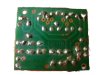
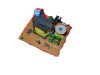
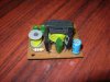
Well, I got hold of a pre-soldered 20W mono audio amp circuit @ a cheap price from an electronics store. The problem is the salesman cudn't tell me where 2 solder the power supply, input and output wires on the board, and the thing doesn't hav a single marking on it xept the name of the manufacturer. I hav attached the pic of the board from different angles, and also a schematic (which i drew) for convenience.Hope u guys'll help me figure what 2 connect where.
I hav no idea what the pinout of the phase splitter-cum-joiner transformer(dats what i think it is). I've just put a pair of 4 dots numbered 1-4, 2 show the connectors in the transformer. Instead of the cap values, i've just copied wats written on them, coz i didn't know how 2 interpret them (bt i guess u wont need 2 know the values). And another thing: I hav marked a few connections with red crosses on the pic---they r joined 2 diodes, but the other ends r not connected 2 anything meaningful. Cud bethey r 4 rectification, if some1 wants 2 put AC in2 it, but even if its so, they rn't correctly wired.

Thanx
 

Attachments

  • dwn-picf.jpg
    dwn-picf.jpg
    25.1 KB · Views: 438
  • up-pic1.jpg
    up-pic1.jpg
    11.5 KB · Views: 430
  • up-pic2.jpg
    up-pic2.jpg
    57.4 KB · Views: 444
god! wats happenin? same pics in 2 posts?? anyways, y do u think its an inverter? Besides the CSD882 transistor is an audio power amp transistor.
 
apakhira said:
god! wats happenin? same pics in 2 posts?? anyways, y do u think its an inverter? Besides the CSD882 transistor is an audio power amp transistor.

I deleted your duplicate post, I presume you clicked twice?.

I think it's an inverter because of the components used, there aren't enough of them for an amplifier. There's no reason to assume it's an amplifier because the transistor is suggested as an audio one.

BTW, where are the other two diodes in your diagram?.
 
I didn't draw them, thinking they didn't hav ne use. Well, if it is an inverter, ne way 2 convert it 2 an amp? I'd thought the transformer was a phase splitter for a push-pull amp. But i hav NO formal knowledge in electronics, even the informal part is also very basic, so it ws just, well, a wild guess.
Shud i redraw the ckt w/diodes 4 u 2 c?
 
apakhira said:
I didn't draw them, thinking they didn't hav ne use. Well, if it is an inverter, ne way 2 convert it 2 an amp? I'd thought the transformer was a phase splitter for a push-pull amp. But i hav NO formal knowledge in electronics, even the informal part is also very basic, so it ws just, well, a wild guess.

No, you can't convert it to an amp.

Shud i redraw the ckt w/diodes 4 u 2 c?

Yes please!. Also try adding the transformer windings, you can use a multimeter on ohms to find which they are.
 
OK. Here's a little revised schematic. I discovered that the the pairs of 2-3 connections inn the transformer are joined 2gether, so i joined them w/dotted line. I've shown the diodes 2 ( i was wrong--1 of the diodes is connected properly). The coil inductaces i cudn't measure--- its gr8r than 2M, and my multimeters 20M setting is slow. When starting from 0, it went up and hovered around 2-3M, but if i started from 1/0, it stopped at around 11-12M.Wierd. I was measuring connections 1-2.
 

Attachments

  • amp-circuit_rev1_108.gif
    amp-circuit_rev1_108.gif
    32 KB · Views: 349
Ain't nobody gonna help me? Pls.. at least tell me why u think its an inverter.. To me it looks like a common collector config...
 
apakhira said:
Ain't nobody gonna help me? Pls.. at least tell me why u think its an inverter.. To me it looks like a common collector config...

It's two power transistors connected to transformer in a self-oscillating configuration, it's a crude inverter - it even had rectifiers to rectify the output.

How can we help?, it's NOTHING like an amplifier, I suggest you take it back and complain!.
 
Well, i'll thanks 4 replying :) Guess i'll hav 2 keep this useless piece, coz these shops r like dat===sell cheap and won't recognize u even if u came the next day 2 complain, know what i mean? U cud help me by suggesting how i cud at least use those transistors 4 a transformerless amp. Quality aint a bi issue--i'm gonna use it 4 a DIY guitaramp. btw, how much do ineed 2 know about electronics 2 know what these kinda circuits do, like u do 8)
 
apakhira said:
Well, i'll thanks 4 replying :) Guess i'll hav 2 keep this useless piece, coz these shops r like dat===sell cheap and won't recognize u even if u came the next day 2 complain, know what i mean? U cud help me by suggesting how i cud at least use those transistors 4 a transformerless amp. Quality aint a bi issue--i'm gonna use it 4 a DIY guitaramp. btw, how much do ineed 2 know about electronics 2 know what these kinda circuits do, like u do 8)

Assuming the transistors are 2SD882's, they are NPN rated at 40V 3A 10W. If you're building a small guitar amp, I would suggest one of the small power IC's, like the TDA2003.

Knowledge comes from experience, obviously age tends to help, it gives you more time to gain the experience.
 
Well, my speaker wont take nething higher than 15W or so, i think. So let me ask a q: if the transistors r rated @ 10W, wat output power wudthey normally provide, and tho i haven't seen 1, cud i hav these 2 as parallel Class A amps? i cudn't get ne other configuration from these 2, can i? In that case, wud u still recommend a power ic, and if so why?

btw, i meant how much hav u studied about electronics 2 b @ dis level (college degree/ just reading a lotta books and practicing stuff/etc.) :D
 
apakhira said:
Well, my speaker wont take nething higher than 15W or so, i think. So let me ask a q: if the transistors r rated @ 10W, wat output power wudthey normally provide, and tho i haven't seen 1, cud i hav these 2 as parallel Class A amps? i cudn't get ne other configuration from these 2, can i? In that case, wud u still recommend a power ic, and if so why?

Yes I would still recommend an IC, building a class A amplifier round those two transistors would cost MORE than building a TDA2003 amp - also a class A amplifier based on those transistors would only have a VERY low output, and you would need massive heatsinks.
 
Well, ok i get ur point, and i'll use a power ic now. So what r the things dat cud b done w/this crude inverter, i mean practical, useful things? btw, can these power ics b "overclocked", i meancan we increase gain from the rated 1?
 
apakhira said:
Well, ok i get ur point, and i'll use a power ic now. So what r the things dat cud b done w/this crude inverter, i mean practical, useful things? btw, can these power ics b "overclocked", i meancan we increase gain from the rated 1?

You could power it up and see what comes out?, other than that it's not of any use - the power input is the bottom left question marks you drew, +ve at the bottom, -ve to the emitters of the transistors.

You can feed power amp IC's from a higher voltage, this will give more power, but will also destroy the IC - the same thing happens to discrete amps as well. If you want more power, use a more powerful amp.
 
put it simply mate u got well and cheated. if you had a bit more knowledge you would probably spotted right away that those trasistor would at least need a heat sink for 20 watts out put as even a 6 w amp has a fairly sized heat sink not to mention a 20 w one. then a transformer output amp is really an old fashioned thing nowadays. but you will learn in time. i know a tv repairer that will tell me the make of a power supply section just by looking at it. well after 8 years at electronics i'm just happy to work out what category a thing comes under from a first glance at it
 
Yeah i wish i had. btw, i didn't think the transformer 2 be an output 1, i thought it was a phase splitter, like 1 found in push-pull amps?
Where's the ouput coming 4m the inverter, the caps with q-marks near the transformer? And the signal input? Why did they put the two sets of caps in parallel, with same cap values and connected 2 the same transformer output?
 
Status
Not open for further replies.

Latest threads

New Articles From Microcontroller Tips

Back
Top