Continue to Site

Welcome to our site!

Electro Tech is an online community (with over 170,000 members) who enjoy talking about and building electronic circuits, projects and gadgets. To participate you need to register. Registration is free. Click here to register now.

  • Welcome to our site! Electro Tech is an online community (with over 170,000 members) who enjoy talking about and building electronic circuits, projects and gadgets. To participate you need to register. Registration is free. Click here to register now.

Pls. check this Analog Switch circuit for Guitar FX

Status
Not open for further replies.

apakhira

New Member
Hi
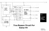
I made a guitar Distortion FX and wanted to add a "soft" True Bypass (DPDT) switch to it. I thought up this circuit (attached here) using the CD 4066 Quad Bilateral Analog Switch type IC. Please check whether it will work fine. Also suggest extra but essential components like caps, etc. (I am a newbie). And what should i do with the unused pins of the CD 4013 (Dual Flip-Flop) and CD 4049 (NOT Gate) ICs?

Thanx
 

Attachments

  • digital_soft_true_bypass_switch.jpg
    digital_soft_true_bypass_switch.jpg
    47.6 KB · Views: 1,082
You do not need the 4049, use the /Q pin 2 instead. Ground unused inputs.
The switch will need a pulldown and debounce. Debounce may cause problems if the clock input is slow.
 
Oh yeah. My mistake. I'll forget about NOT IC then. What do u mean by clock input being slow. It wont be supplied with a wave of pulses. When i'll press the switch only then will it change its state. So will debounce resistor cause problems. And please suggest values for the debounce and pulldown. It'd help if u told me how u calculate their values.
 
You can use the other half of your CD4013 for debouncing. Note that the Q output will be low in the steady state, because when it goes high it resets Q to "0" after the RC delay. Now, when the button is pushed, it clocks a "1" into Q (because the D input is a "1"). Additional clock pulses, due to switch bounce, will have no effect as long as the bouncing ceases before the Reset input reaches the logic threshold.
When Q goes to a "1", the capacitor on the Reset input starts to charge at a rate determined by R and C. the voltage on the cap is

V=9*(1-e^(t/(R*C))) where e=2.71828

Solving for t,

t=R*C*(-ln(V/9)) where ln is the natural log function

Assuming the logic threshold is 4.5V, then t=0.693*R*C

In this case, the width of the pulse on pin 13 will thus be about 15 milliseconds. Most switches stop bouncing in less time than this.
 

Attachments

  • debounce_209.gif
    debounce_209.gif
    3.8 KB · Views: 907
Hi,
The inputs to the 4066 need DC biasing to about half-supply. Then their inputs and outputs need cap coupling.
The input swing to the 4066 must never exceed the supply voltage or go lower than ground from a low-impedance source or the 4066 will be destroyed!
 
Status
Not open for further replies.

Latest threads

New Articles From Microcontroller Tips

Back
Top