Electro Tech is an online community (with over 170,000 members) who enjoy talking about and building electronic circuits, projects and gadgets. To participate you need to register. Registration is free. Click here to register now.
Welcome to our site! Electro Tech is an online community (with over 170,000 members) who enjoy talking about and building electronic circuits, projects and gadgets. To participate you need to register. Registration is free. Click here to register now.
I have design a pll type II with an active filter for obtain the frequency and the phase of a signal, but for some phases of this signal, my exit is at this frequency but with a 180º in phase. How can i do for obtain a 0º phase?? thanks a lot
ok. my circuit is: in the phase detector i have a multiplier, and after that i have the active filter( with operational and RC) for obtain a final phase 0º. My problem is that i have recovered the frequency but the phase, not always is zero, sometimes is 180º, and it depends of the phase in the entry. i want recover the frequency and i want to have phase 0º always.Thanks a lot.
If you are using a multiplier as phase detector, the VCO should be 90 degrees relative to the input. You are doing something strange to get 0 or 180 degrees. I suggest you use CD4066 or 74HC4066 and use the type 2 phase detector. That will give you zero degrees from the VCO.
Another approach (which I have used) is to run the VCO at 4X then divide by 4 with a Johnson counter. The Johnson counter output has 0 and 90 degrees available.
Russ, I was trying to come up with a scenario that would cause this. If this were a digital loop (as in no sine waves), and you divided both the input and the output by two before applying them to the multiplier, they would wind up (I think) consistently either in phase or 180 degrees out of phase, depending on the sign of the VCO transfer function. Now, if you took either the input or the output and divided it by two outside the loop, you could get 180 degree ambiguity. Sorta far-fetched, but it's all I can come up with. And why you would do this, .. :?:
the problem for use this pll (cd40*) is that i want to work at 50Mhz and it can't. Then, i am designing my own model of pll in pspice. I have recovered the frequency but with a RC filter i only recover the frequency; and with the operational filter(active) there are phase at entry that give me 180º in the output. i don't know why....
another problem, have anyone a model for the mixer sa602 or similary in pspice?? thanks
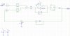
Can you post your Pspice schematic here? Maybe we could answer your question if we could see what you are simulating.
As Russ pointed out, if you are using a multiplier as your phase detector, you should be getting 90º at the output, not 0º or 180º.
Perhaps you already know this, but the frequency doubler in your feedback loop is the cause of your phase ambiguity. When you square a sine wave, the input can be 0º or 180º and you will still get the same double-frequency waveform. What are you really trying to accomplish? There may be another way. Are you simply trying to divide the input frequency by two?
yes. i am going to recover the modulated signal of a bpsk, then i need the frequency in the input divide by two, but in phase. do you know another thing i can do for this?
And do you know a comercial multiplier for do the bpsk?? (multiplie a digital and an AC signal)
thanks for all
Is the 100 mHz input signal BPSK? If so, what is the PLL doing? If you are trying to compare the phase of the 50 mHz signal with the 100 mHz input, you can't do that. One cycle is just like any other! Why not run the VCO at 100 mHz and divide by two at the output?
This site uses cookies to help personalise content, tailor your experience and to keep you logged in if you register.
By continuing to use this site, you are consenting to our use of cookies.