Continue to Site

Welcome to our site!

Electro Tech is an online community (with over 170,000 members) who enjoy talking about and building electronic circuits, projects and gadgets. To participate you need to register. Registration is free. Click here to register now.

  • Welcome to our site! Electro Tech is an online community (with over 170,000 members) who enjoy talking about and building electronic circuits, projects and gadgets. To participate you need to register. Registration is free. Click here to register now.

Please review my design

Status
Not open for further replies.

bag21

New Member
Hello, this is my first post, and my first PIC circuit. My experience with electronics is quite small... when I was a child I had an 100-in-1 electric experiments kit which taught me the foundations but not much more. Anyway I've designed a control device using a 16F871 PIC that interfaces to a PC through an EPP printer port. The purpose of the device is to send commands to an LCD controller such as a SED1335 (in my case a Densitron LM6733) or just as easily a KS0107 or HD44780 (by rewriting the PIC software). The PIC also accepts input from in IR receiver which is used to monitor RC5 remotes, and has an input for the PC ATX Power Button, it also has two LED outputs and a reed-relay switch output which will be connected to the motherboards power button connector on the motherboard its self.

The PIC will be programmed to monitor the EPP interface, the IR Receiver and the power button. The EPP interface provides two sets of 8bit information, either an address byte or a data byte, both of which can both be sent and received from the PC. When an address byte is received the PIC will store it into a "next address" register, and when it receives a data byte it will perform some task using the data byte and the address byte. For example the address byte may mean PORTD which is the output port connected to the LCD Data lines, details to be worked out.

The PIC when monitoring the IR receiver will attempt to process any signal it receives into an RC5 remote control data byte indicating the button pressed and send this information to the PC through the parallel port.
It can be programmed to store the code for the powerbutton on your remote and saves that value in its EEPROM memory so that it will not loose it on power off.

It will also be programmed to turn the PC on and off using the remote by pulsing the relay that is connected to the motherboard power switch connector.

It can draw power from the Wake-on-lan header as well as the standard motherboard 12,G,G,5 connectors.

Finally the PIC has an output pin that can be used to enable and disable to backlight inverter on compatible inverters. It has jumpers to control enable this feature (alternative is always on), and for selecting either 12v or 5v for the inverters power.

The design is loosly based on the design at https://www.tb-electronic.de/vdr/ir_controller.html .

Details of the EPP spec I used for reference are here: **broken link removed**

I would like for any more experienced experts to have a look at my design, see what is missing or if i've made any fatal assumptions. What you think of the design, whether or not you think it will work, any improvements or additions you can think of would also be greatly appreciated.

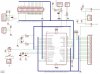
I have attatched a JPG of the schematic done in Eagle. If anyone wants i'll provide the Eagle file.

Here are the details of the signals connected to the PIC:

PIN I/O Destination (/ means active low)
MCLR I EPP /RESET signal
RA0 O LCD /RD Signal
RA1 O LCD /WR Signal
RA2 O LCD A0 Signal
RA3 O LCD /CS Signal
RA4 O LCD /RESET Signal
RA5 O Backlight enable
RB0 I EPP /WRITE signal
RB1 O EPP /WAIT signal
RB2 O EPP INTERRUPT signal
RB3 PULLED DOWN to ensure PGM remains disabled
RB4 I EPP /DATASTROBE signal
RB5 I EPP /ADDRESSSTOBE signal
RB6 I POWER BUTTON IN (connects to power button on pc case)
RB7 I IR RECEIVER INPUT (connects to ir receivers signal line)

RC0...7 IO EPP DATA LINES
RD0...7 IO LCD DATA LINES

RE0 O LEDA enable
RE1 O LEDB enable
RE2 O POWER BUTTON OUT (enables relay that connects to mb power connector)
 

Attachments

  • Untitled.JPG
    Untitled.JPG
    126 KB · Views: 180
bag21 said:
I would like for any more experienced experts to have a look at my design, see what is missing or if i've made any fatal assumptions. What you think of the design, whether or not you think it will work, any improvements or additions you can think of would also be greatly appreciated.

My only query is 'why the EPP port?', why not use the PC serial port?, which is a lot easier to use, a lot easier to connect up, and should be more than fast enough.
 
well i never really considered using the serial port although looking at the chip RC6/7 are also TX/RX lines for the chip, it would certainly free up several pins that i could use for other control purposes, maybe add a few push buttons to the design, or attatch a potentiometer to one of the ADC lines and use it as a volume knob which the PIC could send volume control information to the PC. The reason i chose parallel is simply because in my mind it made the software easier to program the PIC, but I am a competant programmer (although never programmed a PIC before) so using the serial port would not be too much more trouble for me.
 
bag21 said:
The reason i chose parallel is simply because in my mind it made the software easier to program the PIC, but I am a competant programmer (although never programmed a PIC before) so using the serial port would not be too much more trouble for me.

I think you will find that the serial port is simpler to program than the parallel port? (both PC and PIC) - check my tutorials for PIC examples.
 
Nigel Goodwin said:
I think you will find that the serial port is simpler to program than the parallel port? (both PC and PIC) - check my tutorials for PIC examples.

Thanks, that looks interresting, and pretty simple.

With regards to EPP on the PC, sending data to the port as "EPP Data" is simply a matter of doing outbp(LPTBASE + 4, Data), and to send "EPP Address" is simply outbp(LPTBASE + 3, Data). On the PIC side, its simply a matter of waiting for /WRITE to go low, waiting for /DS or /AS to go low, reading the Data port, then pulsing /WAIT high.

As an aside, do you think that i could combine the powerbutton in and out signals connecting them to one pin instead of two, using a set of diodes connected in opposite directions to isolate the input and output circuits from the PIC like:

PB IN -----|>|-----+----- PIC PIN
PB OUT ---|<|-----+
 
bag21 said:
As an aside, do you think that i could combine the powerbutton in and out signals connecting them to one pin instead of two, using a set of diodes connected in opposite directions to isolate the input and output circuits from the PIC like:

PB IN -----|>|-----+----- PIC PIN
PB OUT ---|<|-----+

You can to some extent, but as the pin becomes an OUTPUT to switch the relay, you couldn't turn it OFF again. You also probably need a transistor to feed the relay, and definately require a diode across the coil
 
Just a note, you don't generally need a relay to pulse the power button pins on a motherboard; on every one I've used, one of the two pins is ground, and you simply need to pull the other pin to ground. something as simple as a cheap NPN transistor (such as 2N3904) and a base resistor is enough to do the job, and much smaller and more convenient than a relay.

Also, if you're not too familiar with using PICs, that's an awful lot to get working all at once. at the very least, you should definitely work on the programming in stages; first get it to flash an LED, then try getting the serial interface working, and then move on to things like the LCD, IR interface, or using EEPROM. It would not be a bad idea for you to start off by doing some unrelated, simple example projects to get yourself familiar with all aspects of using PICs.
 
It might be a good idea to either diode-or the 5V lines from the two power supplies so that the WOL power supply doesn't backfeed into the normal 5V from the molex connector.

Might want a pull-up resistor on the button unless you plan on using the internal pull-ups on the PIC.

Some LCDs require a contrast adjustment pot, so you might want to have some space on the board to throw one of these on in case you switch to a 14 pin character display. I've never used a Densitron display so I don't know if it's required.

Otherwise, I'd concur on the serial port and the NPN for the power switch (after double checking the MB of course).

James
 
hjames said:
It might be a good idea to either diode-or the 5V lines from the two power supplies so that the WOL power supply doesn't backfeed into the normal 5V from the molex connector.

Do you mean:

+5V-------|>|---+------
STBY------|>|---+


hjames said:
Might want a pull-up resistor on the button unless you plan on using the internal pull-ups on the PIC.

Well as i said the design is loosly based on someone elses design. That is how they have wired up the power button. I would assume they are using the internal pull-up option available on port B

hjames said:
Some LCDs require a contrast adjustment pot, so you might want to have some space on the board to throw one of these on in case you switch to a 14 pin character display. I've never used a Densitron display so I don't know if it's required.

Fortunately the part i have LM6733 has an inbuilt contrast control circuit so i do not have to feed its Vee or Vo lines, although they are contained on the header.


So everyone thinks I should use a serial interface instead? Thats ok, in some respects better as I could use the on board internal IR header as a serial port so that the device doesnt have any external cables going out of the case to the lpt port. Are there any porblems with using the IR header instead of a serial port when interfacing the PIC?
 
bag21 said:
Do you mean:

+5V-------|>|---+------
STBY------|>|---+

Yeah, that might prevent some head-scratching in the future. (I'd imagine some power supplies might get awfully confused if you hook up the standby power rail to the main one.)

Nearly every cheap character LCD needs an adjustment pot, but if the chances of you needing to attach one are rare...

bag21 said:
So everyone thinks I should use a serial interface instead? Thats ok, in some respects better as I could use the on board internal IR header as a serial port so that the device doesnt have any external cables going out of the case to the lpt port. Are there any porblems with using the IR header instead of a serial port when interfacing the PIC?

Much less software grief using serial (unless you happen to be hacking away on a DOS machine).

I've never tried using the IR header - I'd imagine the voltage levels are TTL/CMOS, but you'll have to check it out. Be careful to not enable actual IRDA modes since I'm not sure if the IRDA modulation is done in the chipset or by the external module. (IRDA has a odd "3/16 encoding", and isn't the same as standard RS232. If you are going to bit-bang the communications, you can work around it though.)

Otherwise I thought nearly every motherboard nowadays had a serial port header on board(if not two) since they never populate both connectors on the back any more.

James
 
I agree the relay isn't necessary for a PC power switch. But, if you do plan to use a relay, the way you have it in your schematic won't work and may blow the pin. A pic output pin can only source/sink 25 mA. I'm pretty sure your relay will pull more than that. use a simple npn transistor driven by the pic

on the serial vs parallel. do what you feel comfortable with. I, personally, would go for serial over parallel but that does require that you spend more effort on the pic and pc defining and implementing a "command set". with the parallel port, you just have to look for a specific pin being set or cleared. with serial you have to look for specific on or off commands. However, if you are communicating text that will be displayed on the LCD, the the serial interface is going to be easier (since it's a character/byte based interface).
 
philba said:
I agree the relay isn't necessary for a PC power switch. But, if you do plan to use a relay, the way you have it in your schematic won't work and may blow the pin. A pic output pin can only source/sink 25 mA. I'm pretty sure your relay will pull more than that. use a simple npn transistor driven by the pic

this is what they used in the design i based mine on, but since everyone seems to say transistors are better (an i guess cheaper??) then i'll go with that.

philba said:
on the serial vs parallel. do what you feel comfortable with. I, personally, would go for serial over parallel but that does require that you spend more effort on the pic and pc defining and implementing a "command set". with the parallel port, you just have to look for a specific pin being set or cleared. with serial you have to look for specific on or off commands. However, if you are communicating text that will be displayed on the LCD, the the serial interface is going to be easier (since it's a character/byte based interface).

parallel in this case would be a lot easier to program as the way i envision controlling the pic will be primarily through software on the pc. using the EPP parallel port the hardware can send either "address" or "data" bytes (it has an address strobe line, and a datastrobe line) and my plan is to send an address byte to indicate which pic register to change, followed by a data byte indicating the data to put in the pics register (ie address = PORTA, data = something) and then use the pc software to do most of the work. for example to draw on the lcd (which is a graphical lcd im using) i would set the address byte to PORTD, then send the data byte as the data i'd send to PORTD, then do the same to PORTA so control the address lines etc to cause the LCD to read the data.

in terms of programming in general i'm a very confident and capable in terms of normal programming languages and concepts, and have had a large amount of experience (by most programmers of my ages standards) in assembly language for various machines so i'm not particularly worried about programming the pic, besides there's plenty of examples on the web that i can use to help me on my way.
 
bag21 said:
parallel in this case would be a lot easier to program as the way i envision controlling the pic will be primarily through software on the pc. using the EPP parallel port the hardware can send either "address" or "data" bytes (it has an address strobe line, and a datastrobe line) and my plan is to send an address byte to indicate which pic register to change, followed by a data byte indicating the data to put in the pics register (ie address = PORTA, data = something) and then use the pc software to do most of the work.

It makes no difference if you use the parallel port or the serial port, you can send 'address' and 'data' just as well with either - but serial is generally far easier, both ends of the link.

But if you're happy with parallel?, it's your project!.
 
Status
Not open for further replies.

Latest threads

New Articles From Microcontroller Tips

Back
Top