Okay so i decided to created a distortion effect that limits the signal.
If the signal looks like a sine, the upper and lower peaks should be
cut off.
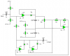
I thought i'd do it with this:

The 10V AC signal represents the input of the guitar. The guitar signal varies from
0-4V according to how hard you strum the strings, but this is just a simulation.
This part still works: if i adjust the two DC sources, i can vary the cutoff value of
the guitar signal. In the picture the sources are 3V and -3V so the signal is cutoff
at 3,7V and -3,7V(including the diode voltage drop).
What i want is to adjust the voltages at the same time using just one potentiometer.
Thats why i builded this adjustable symmetric supply:

The supply consists of a 9V battery and a voltage divider.
By varying the potentiometer i can adjust the V+ and V-(referenced to ground) to
0 to 4,5 and 0 to -4,5. Which is perfect for my guitar signal.
I thought i could now just hook it up to the other circuit(V+ below the first diode and V-
below the second). It doesn't work??!!!
Maybe it's really stupid what i'm trying right now, i am pretty new at circuit design
but i have studied a lot of theory.
Somebody, please help me!!!
If the signal looks like a sine, the upper and lower peaks should be
cut off.
I thought i'd do it with this:
The 10V AC signal represents the input of the guitar. The guitar signal varies from
0-4V according to how hard you strum the strings, but this is just a simulation.
This part still works: if i adjust the two DC sources, i can vary the cutoff value of
the guitar signal. In the picture the sources are 3V and -3V so the signal is cutoff
at 3,7V and -3,7V(including the diode voltage drop).
What i want is to adjust the voltages at the same time using just one potentiometer.
Thats why i builded this adjustable symmetric supply:
The supply consists of a 9V battery and a voltage divider.
By varying the potentiometer i can adjust the V+ and V-(referenced to ground) to
0 to 4,5 and 0 to -4,5. Which is perfect for my guitar signal.
I thought i could now just hook it up to the other circuit(V+ below the first diode and V-
below the second). It doesn't work??!!!
Maybe it's really stupid what i'm trying right now, i am pretty new at circuit design
but i have studied a lot of theory.
Somebody, please help me!!!


") .
. .
.
") .
.