Continue to Site

Welcome to our site!

Electro Tech is an online community (with over 170,000 members) who enjoy talking about and building electronic circuits, projects and gadgets. To participate you need to register. Registration is free. Click here to register now.

  • Welcome to our site! Electro Tech is an online community (with over 170,000 members) who enjoy talking about and building electronic circuits, projects and gadgets. To participate you need to register. Registration is free. Click here to register now.

please help on my circuit

Status
Not open for further replies.

chyun84

New Member
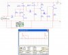
i'm having problem with my circuit shown below....
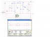
that's a hand clapping circuit and i need help on the circuit...
i've replaced the eletrec mic with the pulse voltge becoz i can't find and mic in the multisim software...
when the pulse is triggered, the output rise to some peak value as shown...
my problem is y the output voltage won't drop till 0V?
the output still maintain at 2V++ even though there's no pulse triggered??
anyone pls give some suggestion and help me with this curcuit,...thanks
 

Attachments

  • hand clap.jpg
    hand clap.jpg
    185.3 KB · Views: 191
They won't drop to 0V, but to a close value.
On the essence, your apparatus is working.

Maybe Q2 is not correctly biased.
Maybe Q3 is not correctly biased as well.
I think R5 value (100 ohms) is too small for a transistor like BC548 (Q3), you should add another resistor on Q3 base.
R2 is at 0 ohms.
 
Last edited:
Hi, chyun

Before the experts get in here and muddy things up, I suggest you remove the capacitor C2 and resistor R1 from your circuit, and see what happens.

Regards,
AllVol
 
Last edited:
hmm.... thanks for all the suggestion...
after several of modification, i change some value of the components and i get the output as shown....
i also changed the supply voltage from 4.5 to 6v
but i got few questions..
- izzit my circuit ok for now?
- can i connect the output to my pic16f84 microcontroller?
- is the output voltage enough for the input of microcontroller?
- any modification of the circuit i need to do??

pls give more suggestion thanks....:)
 

Attachments

  • modified.jpg
    modified.jpg
    311.7 KB · Views: 140
Looks like you have 5VDC out. If so, A 5volt PIC can read that. Maybe a current limiting resistor or diode if you are worried, and check it with a meter on a breadboard. What are you working on? The simulation shows 2 V/div on trace B from what I can see.

I use a PIC on an RC time constant for a project I just did and it worked well. Are you going to use an interrupt or poll the pin?
 
Last edited:
hmm..... what do u mean by interrupt or poll the pin??
waht i'm working on is that when i clap the hands, the pulse will be sent to the microcontroller as and input, and it will drive the servo motor...
actually i'm not very familiar with the pic16f84 and which pin should i connect as an input for pic1684?? pin4 or......
 
Got it. There is a good 556 version of the clap switch (clapper) on the internet and a link to it here if you search electro-tech-online. I did one back in the early 80's with an opamp. I still have it and it still works. :)

If that is all you are doing, polling the circuit is fine (set it for input, and read it over and over util you see the a high ). Maybe some debounce as well.

You might want to download mikrobasic or proton basic, trial version of BASIC for the pic (proton gives you 50 lines, so enough for this project so far). Mikrobasic would work for sure.

OR see if Nigel has a servo tutorial. He will have something that will apply
if you want to do it in assembler.

If you use BASIC, the pulseout command can be used (on most of them) to move the servo to the position you want.
 
You can use port A or B, you just pick a pin and TRISA or B (to set it for input)

Or get BASIC, it does most of the PIC setup for you, and you just tell it the
direction of the pin you hooked up to..

You have a programmer and programming software right?
 
i'm trying to pogram it using picBasic, but i don't have any idea about the language of picBasic....
do u mind to give me some idea about it and can i find manual for it on internet??
 
Who is picbasic by (to me they are all picbasic)? Is that MELABs? I have the standard of that one (yuck). Let me know if that is the one you have? I will send a sample in that or or proton, just pick one.
 
i think its MELABS (not very sure)...
oh ya.. by the way.. just now u mention about the 555 clapper switch, izzit this one?? **broken link removed**?? izzit suitable for my project?? how much its output voltage??

do u think my circuit works fine?? i dont feel like to change if mine one works well..:)
 
Here, you can mod this for what you need, hope this helps.
I will not tell you it will work first time, but it will get you started.
Check the switch (pulse logic) and you will have to change the pup and pdown to where you want the servo to go.

Code:
' Quick program to read a switch/pulse, blink an LED when the is pulse is seen
' and move a servo, based on state (up or down)
'
'set you pin directions input ot output 0=clap circuit 1=servo 2=led
input 0
output 1
output 2
'equates
symbol switch = pin0
symbol servo = 1
symbol led    = 2
symbol state = b0
symbol pup = 210     'position to send servo to pup and pdown
symbol pdown = 105   'best down  only move up  timing below pretty good25ms
symbol c   = b1

symbol down=0
symbol up=1
goto init

loop:
if switch = 0 then loop

if state = down then goup

init:
state=down
for c = 1 to 15
    pulsout servo,pdown
    high led
    pause 35
    low led
next
low led
pause 1000
low led
goto loop

goup:
state=up
for c = 1 to 15
    pulsout servo,pup
    low  led
    pause 35
    high led
next
high led
pause 1000
high led
goto loop
 
Last edited:
chyun84 said:
just now u mention about the 555 clapper switch, izzit this one?? **broken link removed**?? izzit suitable for my project?? how much its output voltage??

do u think my circuit works fine?? i dont feel like to change if mine one works well.

That is the one, it will work fine. But like you, if you did all that work, you learned and had fun (most of the time). I would keep my circuit too.

Have you thought about a zener or something on the input (pin0) I think it
was in the software.
 
thanks very much for the code... i'll try to learn and test it.. any question i'll ask again..
oh ya.. another question...
my circuit will work as stated below:

- clap once = servo motor rotate half revolution (one step forward for biped : left leg)
- clap once again = anoter half revolution (another step forward for biped : right leg)
- clap twice = servo motor continue rotating without stop (biped continue walking)
- clap thrice = servo stop (biped stop)

my question is..
for the 'clap twice' section, can i set the time needed for the microcontroller to receive the the pulse.. for example = can i set 2 seconds for the microcontroller to detect how many claps had been clapped?? if 2 claps detected, then the servo will continue to rotate...
and if 3 claps detected, then.......

izzit possible to write the code for my question??
 
You would modify loop:

Set a flag when you see the first clap and start a timer counter (also bump a variable/counter for each clap so you know how many after if goes back low). But keep looping, the flag is for you to know you have received the first clap and you use it to determine the time you stay in the loop (via the timer counter variable value).

When you leave clear the flag, see how many claps.

Might have been easier to write it than explain. :) But you have to
do some of the work :D (now I see how Nigel puts those things in).
 
hmm....seems confusing right now...
i'll try to understand it and write again... anyway thanks for the help..
any problem i will post here again...

BUT, seems like my question had help u understand 'how Nigel puts those things in' hehe.. how u going to thanks me, lolz
(just kidding only..hehe)
 
hehe.. Yea, if you get stuck mail me. Or, I can write the code for you and you
can send me a working unit. :eek:

Wife is tring to get me away from my computer right now, otherwise I would rough the code for you. What I sent will work for 1 clap to see the servo move back and forth. You need a flag to show first clap, a timer to stop watching claps, and a clap counter. It is not that hard. Looks at the code and you will see how picbasic works. Did you buy standard or pro?

I did a two servo bot, idea came from Nuts & Volts MANY years ago. Worked well. I did it all my way of course, but got the idea there. I have the code somwhere. Simple. move to servos to have it walk..

My son took it to school with a report and pictures. They had to leave the project for some reason. The teacher retired that year. BOT never came home. :mad:

BOTnapper..
 
lolz.. Botnapper....
i think i will email u if i got problem for the code...
i will sent u the working projects after i finish too.....
i've found the biped walking robot which required only 1 servo motor to run... and it need times to contruct.. ^^

about the PicBasic, i also not sure which type because its in my Uni labs and i havent try it.. so not sure what types...
anyway thanks for all the help and suggestion.....
 
That is KEWL! I have a couple servo (not modified around here), the rest I could play with.. You should fill in your location in the profile. We are you located.

I know what you mean on time. I need to get busy here.

If a University it is probably MELABS. It should compile and run like it sits (just set uC and speed). EMAIL if you have any problems. Will not hold you to sending one, but love to see it..
 
Status
Not open for further replies.

Latest threads

New Articles From Microcontroller Tips

Back
Top