Continue to Site

Welcome to our site!

Electro Tech is an online community (with over 170,000 members) who enjoy talking about and building electronic circuits, projects and gadgets. To participate you need to register. Registration is free. Click here to register now.

  • Welcome to our site! Electro Tech is an online community (with over 170,000 members) who enjoy talking about and building electronic circuits, projects and gadgets. To participate you need to register. Registration is free. Click here to register now.

Please help me recognize clamp-meter's cap ratings for replacement

Status
Not open for further replies.

BGAmodz

Member
Hi everyone in this forum .

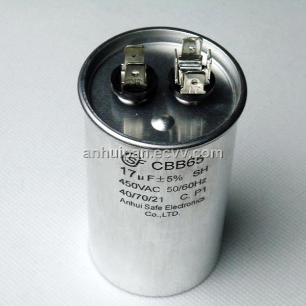
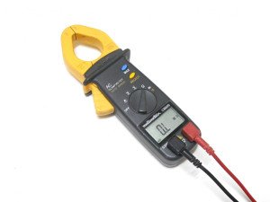
So 2 days ago i was trying to repair a microwave , i decided to check a big AC capacitor with a clamp meter , i used AC voltage mode , and the meter just shut down as soon as i connected the probes to the AC capacitor .
I opened the clamp meter and found that 2 tracks were out of place and a small capacitor was burned but only 4 symbols were visible in it : YP and 02 , i wonder what rating would be safer to use , this capacitor is attached to a small daughter board making connection between the probes holes and the meters motherboard .
this is how the capacitors looks like :

Microwave's cap :
China_450v_17uf_AC_Capacitor_CBB6520119231416233.jpg

Meter's cap :
zEkd9Ra.jpg


Multimetrix CM600
2870d4e57208c022e36c9320a0cfa408-1894922-300_300.jpg
 
i used AC voltage mode , and the meter just shut down as soon as i connected the probes to the AC capacitor .
Not quite sure what you did. How do you connect a clamp probe to an out of circuit capacitor?

John
 
If the blown "capacitor" is connected between the probes then it's not likely to be a capacitor but much more likely to be a varistor, used to protect the meter input against excess voltage. In any good design I would have expected a fuse in the input circuit somewhere between the varistor and probes to also protect against over current situations. Take some photos of the input and surrounding circuitry and post them here :)
 
The meter should work with out the TVS. Since the instructions say protected to 660 VRMS, that's what I'd go for. Use this **broken link removed** as a start.

Now use size/lead spacing to narrow down the part.
 
I would SERIOUSLY suggest you leave microwave ovens alone, you obviously have no clue about how they work (it was an incredibly stupid thing to do, and was guaranteed to blow your meter). Microwaves are the most dangerous of all household appliances, and the shock from that capacitor WILL kill you.
 
I would SERIOUSLY suggest you leave microwave ovens alone, you obviously have no clue about how they work (it was an incredibly stupid thing to do, and was guaranteed to blow your meter). Microwaves are the most dangerous of all household appliances, and the shock from that capacitor WILL kill you.
I admit it i really acted stupid and could have killed my self
 
The meter should work with out the TVS. Since the instructions say protected to 660 VRMS, that's what I'd go for. Use this **broken link removed** as a start.

Now use size/lead spacing to narrow down the part.
Thanks for this , but what about the capacitance ratings in xfarads ??
 
Last edited:
The unit does not turn on , am sure if its not the varistor , its some damaged tracks .
I have just read about this varistor's behavior :
actually varistors may not be able to successfully limit a very large surge from an event like a lightning strike where the energy involved is many orders of magnitude greater than it can handle. The high current resulting from the strike generated excessive current that destroyed the varistor in my case .
 
Last edited:
I would suggest buying a new meter - you've probably caused extensive damage to it, far beyond anything it's 'protection' is capable of handling.

They aren't designed to have 3000V high current applied to them :arghh:
 
the card contain small amount of SMD parts , i checked them and they seem fine , just some resistors and zener diodes , am pretty sure it will work again when i replace the varistor .
 
I would suggest buying a new meter - you've probably caused extensive damage to it, far beyond anything it's 'protection' is capable of handling.

They aren't designed to have 3000V high current applied to them :arghh:
I taught that the CAPACITOR was only delivering 220 V ac !!!
 
I thought the part INSIDE your meter is a (Transient Voltage Suppressor), not a cap. The TVS basically ACTS like back to back Zenier diodes. It's physical size determines how much energy it can absorb.

It is usually placed in Parallel with what's being measured to act as a clamp. Removing it, should allow the meter to work without any protection. So, your first step is to remove it, repair the tracks and see if the meter works.

As for the cap in the microwave, here is a pic of one. https://www.appliance-parts-experts.com/13QBP21090-capacitor.html Note the 2,100 Volts AC rating. That should be enough to SCARE you and easy enough voltage and current to kill you.

I worked on stuff a but more scary. An X-ray diffraction set with a 100 KV, 0.1 A power supply and an electron beam evaporator that had a 15 KV, 1 Amp supply with a Shunt Tube/Valve regulator and a 1000 W rube RF transmitter. If you don't know what your doing, you don't mess with it.
 
Last edited:
I thought the part INSIDE your meter is a (Transient Voltage Suppressor), not a cap. The TVS basically ACTS like back to back Zenier diodes. It's physical size determines how much energy it can absorb.

It is usually placed in Parallel with what's being measured to act as a clamp. Removing it, should allow the meter to work without any protection. So, your first step is to remove it, repair the tracks and see if the meter works.

As for the cap in the microwave, here is a pic of one. https://www.appliance-parts-experts.com/13QBP21090-capacitor.html Note the 2,100 Volts AC rating. That should be enough to SCARE you and easy enough voltage and current to kill you.

I worked on stuff a but more scary. An X-ray diffraction set with a 100 KV, 0.1 A power supply and an electron beam evaporator that had a 15 KV, 1 Amp supply with a Shunt Tube/Valve regulator and a 1000 W rube RF transmitter. If you don't know what your doing, you don't mess with it.
I hope this picture could give you a clear idea , here is where the component is connected ( between positive hole and the motherboard ) :

OCOLblL.jpg
 
Last edited:
It should basically be across the input which I can't tell. A cap would just be used for the AC scale.

So. are those binding post jacks used for AC only? If so, then it could be an "X" or "Y" capacitor. Probably "Y".

If it is a capacitor, I'd pick it out of this list https://www.digikey.com/product-search/en?pv14=1140&FV=fff40002,fff8000b,654056a&k=capacitor&mnonly=0&newproducts=0&ColumnSort=0&page=1&quantity=0&ptm=0&fid=0&pageSize=25 by diameter.

The cap picked is a a "safety capacitor". The value probably isn't critical. So, I'd try to pick it by size.

I can't quite see what the circuit looks like, but if in series, it may be a cap. If in parallel, its probably a TVS. If the posts are only used for AC, thats another hint.

Temporarily, you can connect a ceramic cap of a high enough voltage, but I would only use a safety cap for a final repair.
 
Last edited:
Status
Not open for further replies.

Latest threads

Back
Top