Continue to Site

Welcome to our site!

Electro Tech is an online community (with over 170,000 members) who enjoy talking about and building electronic circuits, projects and gadgets. To participate you need to register. Registration is free. Click here to register now.

  • Welcome to our site! Electro Tech is an online community (with over 170,000 members) who enjoy talking about and building electronic circuits, projects and gadgets. To participate you need to register. Registration is free. Click here to register now.

please help me for getting ad 620 instrumentation amplifier output correctly.

Status
Not open for further replies.

shibas

New Member
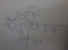
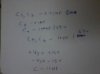
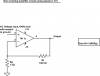
Iam posting my circuit diagram of the Ad 620 instrumentation amplifier and the values of components used in the circuit in two separate attachments.please refer to it and mention any change if i have to make to the circuit to get the amplified output.When i connected this circuit first i was not getting the required gain.But now iam getting very huge gain than the gain that is required.The gain equation for ad 620 is G=(49.4k/rg)+1. isn't it? I need a gain of about 100 or below 100.please help me.I used the 0.1 uf capacitor between the input signal and the non inverting input to remove the dc offset components.Is that correct to use it?

Do i need to insert a resistor between the inverting and non inverting input terminals of the op amp and ground that resistor to reduce the effect of the input bias current?
Some body please help me.

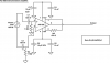
If the circuit diagram is wrong somebody please reply or upload a correct circuit diagram of the instrumentation amplifier using ad 620 ic.
 

Attachments

  • circuit diagram.jpg
    circuit diagram.jpg
    74.6 KB · Views: 351
  • component values.jpg
    component values.jpg
    71.4 KB · Views: 333
hi,
You must have a DC path to 0v on the 100nF capacitor input.

I have shown a 100K
E.
 

Attachments

  • AAesp01.gif
    AAesp01.gif
    31.2 KB · Views: 320
Why use an instrumentation amplifier when your input is unbalanced? Use an ordinary opamp instead.
An instrumentation amplifier or an opamp cannot drive the output capacitors. If you want a lowpass filter then use a lowpass RC filter.
 
741 0pamp ic amplification problem

Iam using a vibration analyzer or sensor.I need to amplify the above sensor's output signal.For this purpose i used opamp ic 741 in the non inverting configuration.But when i gave the input to the amplifier from a function generator the amplifier gave a gain of about 50 and 68 initially.When i changed the input frequency from the function generation to 1 khz amplifier gave a gain of 100 even though the amplifier circuit was originally designed to give a gain of about 101.

But for my application,when i give the input to the amplifier from the output of the vibration analyzer the gain of the amplifier circuit changes to a huge value of about 450.

What may be the reason for this?

At first i used AD620 ic for the amplification instead of the op-amp ic 741.The behaviour of the gain at that time was also similar to now.

Somebody please help and reply fast.
 
hi shibas,

Please post a circuit, a 741 is not really suitable for a vibration analyser, its got a very poor specification.

Whats the range of frequencies you want to cover.?

E.
 
hi shibas,

Please post a circuit, a 741 is not really suitable for a vibration analyser, its got a very poor specification.

Whats the range of frequencies you want to cover.?

E.

Indeed,
Without proper info, our crystal balls become very fuzzy and fogged.

But if I had to make a guess, I would say that you have a capacitor somewhere in the feedback path that is changing your frequency response.
Again, this statement comes from a fogged crystal ball.
 
For amplifying the output of a vibration sensor.

I am posting the circuit diagrams of both the amplifiers:-

1.circuit of AD 620 instrumentation amplifier,designed for getting a gain of about 106.

2.circuit of non inverting amplifier using op amp ic 741,designed for getting a gain of about 101.

The gain equations of both the amplifiers are written inside a box near both the circuit diagrams iam attaching with this post.

I tried both the above amplifiers for amplifying the output of a vibration sensor or analyzer.

But when i gave the input from the function generator both the circuits amplified well.

For the non inverting amplifier using 741 ic,when i gave the input from the function generator at first i was getting a gain of about 50 and 68 when the input signal frequency was about 9.7 KHz.When i changed the input signal frequency to about 1 KHz i got the gain of about 100.But the original gain designed for this amplifier circuit was 101.When i gave the sensor output signal to the input of the non inverting amplifier it gave a gain of about 450.


When i used AD620 amplifier circuit,I get a gain value of about 100 when i was giving input signal from the function generator.When i gave the output signal from the vibration sensor as the input to the AD620 amplifier it also gave about a gain of about 450.

Why is the gain becoming very high when i give the sensor output as the input to the amplifier?

Which amplifier should i use for my need(for amplifying the sensor output)?

Should i make any modifications to my circuit.If then please suggest those modifications clearly.

Somebody please help me and reply fast.
 

Attachments

  • ad620-instrumentation-amplifier.png
    ad620-instrumentation-amplifier.png
    20.3 KB · Views: 1,383
  • noninverting-amplifier-using-741.png
    noninverting-amplifier-using-741.png
    20.4 KB · Views: 981
I wonder if the output from your vibration sensor is changing when you connect it to the opamp, giving the illusion of increased amp gain? That would be the first thing I'd check.
 
I need to cover the range upto 1 KHz only


Hi,
This is what I see in simulation, +/-10mV 1KHz signal input with +/-1V output ie: gain ~100

How are you connecting the function generator to the AD620.??
 

Attachments

  • AAesp03.gif
    AAesp03.gif
    41.4 KB · Views: 281
The non-inverting input of the 741 opamp needs a DC path to ground.
Its datasheet shows that its maximum gain at 10kHz is only 50 to 70.
 

Attachments

  • uA741 frequency response.PNG
    uA741 frequency response.PNG
    11.7 KB · Views: 460
I think it’s a little thing called Gain Bandwidth Product:

https://en.wikipedia.org/wiki/Gain–bandwidth_product

BW = A*GBW where BW is the bandwidth, A is the gain, and GBW is the Gain Bandwidth Product.

In my example, when the input signal freq was 9.7KHz i got a gain of ~50 for a GBW of 9.7K * 50 = 485KHz, which confirms with the low end of the spec for a 741. So, if the GBW of my 741 is 485KHz then at 1KHz, we can expect a maximum gain of 485KHz/1KHz = 485.


If i insert a low pass RC filter in between the vibration sensor output and the 741 op amp input will the gain become alright?I think some times the vibration sensor output will be at very high frequencies.So a low pass RC filter may remove these high frequency components.
 
Which is the simulation software you used?

hi,
I use LTSpice, its free,
This link has the program, also if you sign up to the user group there are lots of examples

**broken link removed**

E.
 
Halo ericgibbs.

Which simulation software did u use for drawing the circuit diagram with the simulated input and output diagrams in the above post and also for simulating the input and output signals as shown in the above post?

I used LTspice 4 software for both AD620 instrumentation amplifier circuit(for the circuit using AD620 ic as shown in your post with simlated input and output) and also i used LTspice with the non inverting amplifier configuration using UA741 ic.I think both the AD620 and UA741 ics were not available in the LT Spice 4 software's library when i searched to insert them in the circuit diagrma from the library.

I dont know whether i have done the simulation steps for both the input and output signals the right way.Can you explain the correct method of drawing the circuit diagram using the simulation software of LT Spice and then simulating that circuit diagram for both input and output signals for me and also how to insert the different ICs and other different components from the library?We can insert the components from any where other than from the library know?Or can we insert some other Ic available in the library of the software of LT spice and edit the name of the ic and then use it?Is that method correct?

Did u use the LT Spice 4 version or some other version of LT Spcie?
 
Last edited:
hi,
If you sign up for the Yahoo LTSpice user group, the link I posted, you will find the AD620 and 741 OPA's.

Look in Files/Lib folder on that website, scroll down through the files and then download the AD630 and LM741.zip files.

**broken link removed**

**broken link removed**


If you get stuck , come back here.:D

E.
 
Status
Not open for further replies.

New Articles From Microcontroller Tips

Back
Top