Continue to Site

Welcome to our site!

Electro Tech is an online community (with over 170,000 members) who enjoy talking about and building electronic circuits, projects and gadgets. To participate you need to register. Registration is free. Click here to register now.

  • Welcome to our site! Electro Tech is an online community (with over 170,000 members) who enjoy talking about and building electronic circuits, projects and gadgets. To participate you need to register. Registration is free. Click here to register now.

Please help light + dark sensor

Status
Not open for further replies.

Hacks

New Member
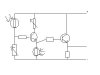
I have designed a light + darkness sensor. It basically is a darkness sensor circuit conneted to a trasistor which is in between the LDR and resistor (this part is ovisouly the light sensor part) providing the potential difference this in turn goes to atransitor which when activated turns on a LED I WAS successfull in getting the LED to light but I want to take an output into a Logic gate circuit.

P.S How do you post diagrams?

Thanks in advance.
 
DJ_ReL@X! said:
Add your diagram in .jpg format as an attachment.

Not JPG, JPG's are poor quality and large file sizes for graphic diagrams, using GIF gives perfect quality and much smaller files!. Leave JPG for photos or scanned images, where the lower quality doesn't matter, and the compression works better.
 
Right thanks, here is a diagram of my circuit , could anyone please help me I'm using a 9v battery to power the circuit but I have noticed that the voltages coming out of the output are to close together to work when used as an input for a logic gate circuit.
 

Attachments

  • circuit_634.jpg
    circuit_634.jpg
    9.8 KB · Views: 1,334
Hacks said:
Right thanks, here is a diagram of my circuit , could anyone please help me I'm using a 9v battery to power the circuit but I have noticed that the voltages coming out of the output are to close together to work when used as an input for a logic gate circuit.

That's a pretty poor circuit, far better to use an opamp as a comparator, have a look at , figure 12.

Here's what I meant about GIF as opposed to JPG, the same image here as a GIF is less than 1/3rd of the size!. [/quote]
 

Attachments

  • circuit_634.gif
    circuit_634.gif
    2 KB · Views: 1,272
Thanks Nigel but leave my circuit out of it! Only messing! But I already had a look at that page and I can't understand any of it!! You see I'm building this circuit as part of a school project.So naturally any help on the matter is much appreciated. Thanks anyway with the info. on posting the diagrams.
 
Sorry but I failed to mention what the circuit is supposed to do. You see I need the first LDR (the one on the far right) to ativate the transister when it gets no light shone on it this then allows the second LDR to turn the second transister on when it gets light shone on it.When this second transister is on it allows the electricity to flow out (the output) and Into a LOGIC gate circuit. But the problem I have is that I'm running the circuit on 9v and the output voltages are too close together to operate the LOGIC gate circuit.I am only allowed a max. voltage of 12v. Could anyone please help me.
 
Try with a lower resistance in the base of the BJT. Could you please include the values on your diagram?
 
I have to warn you all resistance values are very approximate.
 

Attachments

  • circuit_193.gif
    circuit_193.gif
    3 KB · Views: 1,208
Just by looking at it very fast, I think you'll have to place the resistor (of, say, 10K) in the collector (between 9V and the second transistor's collector), and remove the resistor from the emitter (connecting the emitter to ground).

I don't really get the purpose of the top LDR (between +9V and collector of the first BJT). Maybe you could explain a bit better what u'r trying to do?

Another thing, why going with a common collector, when it's muc easier (and appropriate) to go with common emitter configuration?

TI|CP
 
Status
Not open for further replies.

Latest threads

New Articles From Microcontroller Tips

Back
Top