Continue to Site

Welcome to our site!

Electro Tech is an online community (with over 170,000 members) who enjoy talking about and building electronic circuits, projects and gadgets. To participate you need to register. Registration is free. Click here to register now.

  • Welcome to our site! Electro Tech is an online community (with over 170,000 members) who enjoy talking about and building electronic circuits, projects and gadgets. To participate you need to register. Registration is free. Click here to register now.

Please Help Digital Clock Schematic Needed ASAP

Status
Not open for further replies.

bob_the_builder

New Member
Hi

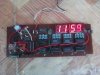
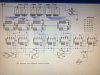
If anyone would like to help and draw a schematic (preferable done on a computer) for a digital clock it will be greatly appreciated. The schematic is only for personal use. The schematic should be a 12 hour clock (including hours, minutes and seconds)

There is what the schematic should include:

- 6 number displays

- Use of transistors

- 7490 and 7447 chips

The 10th hour hand should no display anything until the value is 1 but the 10th min. can display a zero and so will the 10th second.

Thanks for you help, it is super greatly appreciated

bob_the_builder
 
Im a newbie here. I hd made 24hours clock base of 7490, 7447. But here in this forum had a post of that clock schematic. Mine has a little different of 4 transistor and one more for the second flicker. I go here to looking for a solution of preset buttons to adjusting the numbers. the glitching in a push button switch problem.
 
Im a newbie here. I hd made 24hours clock base of 7490, 7447. But here in this forum had a post of that clock schematic. Mine has a little different of 4 transistor and one more for the second flicker. I go here to looking for a solution of preset buttons to adjusting the numbers. the glitching in a push button switch problem.

here the clock I made that doesnt have preset switch
 

Attachments

  • Photo0446.jpg
    Photo0446.jpg
    123.3 KB · Views: 180
here I post my simple design of 12hours with displaying numbers every 10 seconds for a minutes and 10minutes for an hour. Pulse at input is 1 Hz. May be this is the clock you mean.
Notes: every input pins of 7segments display that connected to 7490 should be add of 330ohm resistor.
 

Attachments

  • TwelveTenTenClock.jpg
    TwelveTenTenClock.jpg
    214.4 KB · Views: 181
Last edited:
Sory bob. theres something mistake in the schematic, U16 must be deleted and the 1Hz pulse shoud be connected to Clk1 of U13.
 
Status
Not open for further replies.

New Articles From Microcontroller Tips

Back
Top