Electro Tech is an online community (with over 170,000 members) who enjoy talking about and building electronic circuits, projects and gadgets. To participate you need to register. Registration is free. Click here to register now.
Welcome to our site! Electro Tech is an online community (with over 170,000 members) who enjoy talking about and building electronic circuits, projects and gadgets. To participate you need to register. Registration is free. Click here to register now.
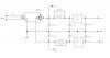
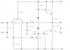
The first two transistors are a differential amplifier. The next transistor (BC546) inverts the signal and adds gain, the diodes compensate for base-emitter voltage drops in the final stage (or attempt to, seems to be missing a couple of diodes). The remaining transistors form the drive circuit, a class B emitter-follower Darlington drive stage.
Yes it looks like it may be missing two diodes unless that is part of a scheme
to decrease crossover distortion. Seems like that would cause a lot of
power dissipation in the transistors however. Maybe that is why it burnt out.
Try two more diodes in series with the ones that are already there.
The 150pf cap is most likely for compensation.
The 10uf cap (working with the 4.7k and 100k) is most likely to increase AC gain of
the whole circuit without affecting dc bias point.
No, the missing diodes will INCREASE cross-over distortion, as the outoput stage will run in class B.
Seems like that would cause a lot of
power dissipation in the transistors however. Maybe that is why it burnt out.
Try two more diodes in series with the ones that are already there.
Adding two diodes may well cause it to overheat and destroyut itself, as it stands there's zero dissipation in the output stage at idle.
Personally I'd never use that crude method of biassing, you're asking for thermal runaway or crossover distortion - I'd use a Vbe multiplier and adjust accordingly.
A class-AB amplifier can use a few diodes or a Vbe multiplier for bias. If they are mounted on the same heatsink as the output transistors then they actively change the bias current with temperature change so that the current is always correct.
thank you for everybody but I have new problem. The one side of power amp is fault I measure a voltage output it is 150 mv but when I try to play it has not sound out at speaker. where I should check
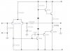
The BC546 transistor in your power amplifier is a common-emitter type. It inverts.
When the signal causes its base current to increase then its collector current also increases. The current increase at its collector causes more voltage drop in the resistor in series with the collector so the collector voltage drops.
When the signal causes its base current to decrease then its collector current also decreases. Then the voltage at the collector increases.
I am sorry for an error in the schematic
This is the new schematic
Please help with this the problem. The one side of power amp is fault I measure a voltage output it is 150 mv but when I try to play it has not sound out at speaker. where I should check
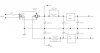
Your power supply schematic shows a positive regulator named 7615. I've never heard of it. Please provide data sheet. Power supplies like this often don't work without protection diodes across the regulators.
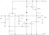
Also what is the upper output transistor? Is it BC546 like the numbers written next to it say?
I am sorry for schematic my friends sent it to me does not clear this is the new schematic.Now it is working but is not 100% because the little problem about balance in tone control I will sent my power amp to my teacher this monday. Thank you for every advice
You could eventually put a potentiometer in series with the two diodes to adjust the bias current of output transistors. Also you can put diodes on the same heatsink with output transistors for temperature tracking.
This site uses cookies to help personalise content, tailor your experience and to keep you logged in if you register.
By continuing to use this site, you are consenting to our use of cookies.

")