Continue to Site

Welcome to our site!

Electro Tech is an online community (with over 170,000 members) who enjoy talking about and building electronic circuits, projects and gadgets. To participate you need to register. Registration is free. Click here to register now.

  • Welcome to our site! Electro Tech is an online community (with over 170,000 members) who enjoy talking about and building electronic circuits, projects and gadgets. To participate you need to register. Registration is free. Click here to register now.

Plasma SMPS, help to confirm problem with it. Have a pinout chart

Status
Not open for further replies.

fastline

Member
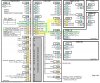
I am trying to fix this plasma TV. Basically when power is applied and all boards plugged in, there is a relay click on the PS, a cooling fan runs for a few seconds, then the system shuts down with a red blinking light. I found the attached pinout of the PS and trying to verify if the PS is actually my culprit since I just cannot find much wrong with it yet.

I am looking for an experienced TV tech to tell me if the "standby" pins should see power all the time whether anything is plugged into the board or not? When I apply 120V to the board with absolutely nothing plugged into it, I get 5VDC on the standby pins that call for it but there are no other voltages present. If I should see these standby voltages on the bench, that would just confirm that I am at least on the right board.
 

Attachments

  • 2009-10-15_025924_seine1.jpg
    2009-10-15_025924_seine1.jpg
    122.2 KB · Views: 431
Thought I would try a bump here. Are there no TV repair guys here? I thought this might be a simple question. Not enough info to go on?
 
Unfortunately you rarely get circuits for Plasma TV's, repairs normally consist of board replacements, while they are still available.

If only the standby voltages are present, it 'probably' means either the main PSU section is faulty, or it's not been instructed to turn on by the control section.

Presumably the PowerSig line is what turns it on?.
 
Maybe I was not clear, some of the standby voltages are NOT present. I was tracing through the board and it looks like the bridge, and main part of the PSU is not active until the relay fires over. That being said, if the "standby" voltages should be on as soon as the board is plugged into power, there is certainly something wrong with the board. I guess it is "somewhat" easier to trouble shoot since about 90% of the PSU is dead until the relay is fired so tracing is somewhat easier. That being said, I am still trying to figure out how AC power is being conditioned for the standby outputs. I DO have the 5V out but that is it. All my transformers, power caps, bridge, etc are all dead without the relay switching.

I was just hoping to find someone that has experience in troubleshooting to say "yeah, if the standbys are missing, there is an issue with the board". Or, maybe there is still some type of switching circuit here to turn on these standby voltages.
 
That is why I posted the diagram because it lists I think 3 standby voltages. There is a 12V, 20V, and I think 32V listed on the sheet above. Of course this may all be hearsay if that chart is not right because it was just an Inet find....

I was able to find a new board for 100 bucks from a guy but I guess I do not like to get beat and still trying to educate on SMPS repair since I keep running into it. I could be chasing my tail if 5V is all that is supposed to be present.
 
Possible find??

In tracing voltage all over the board, it seems power is coupled to the output side with optocouplers. I still cannot trace down how exactly things are laid out. As you might imagine with like 6 different voltages, it is a busy board. Anyway, the attached includes the data sheet for a line of 4 of these critters. IIRC, you can test the diode side just like any other diode which tests bad or OL on 3 out of 4 of them. I have to really wonder what killed them if they are bad though. Has to be something else to this...

Do these components sound dead if a diode test shows OL from 1-2? The 4th reads .75V drop in both directions but I would pull them all for bench testing.
 

Attachments

  • mXyzqqty.pdf
    685.5 KB · Views: 337
Look at the the color code chart. It tells you which signals are present always! I'd be looking at POWER_ON and ALARM signals as well.
 
HUH,,,, I went and grabbed a familiar meter instead of this new one and wouldn't you know it, the opto diodes are testing fine.... What a POS meter... makes me wonder what else it sucks at..
 
Well, I would post that up but as an update, it is now looking like the PS board is just fine and there may be a short somewhere that is faulting it. I plugged in ONLY the one plug that would initiate the relays and the board basically comes up, goes back down for a sec, then back up and stays up. I think it is a sort of boot up test that it does. Anyway, ALL of the standby voltages are present. The second that I plugged in the plug supplying 12V and 20V and tried to fire it up, it booted, then came right back down. I further tested with the plug that has the main switch and it stayed up as well so I think what I am looking for is a short somewhere that is putting the supply in a fault condition. At least that is where I am as of now. Subject to change in 10 min... Guess maybe this is why I could not find anything wrong with the PSU, it might be fine..
 
Confirmed now that board will stay hot and all voltages are present when all but the P807 connection is made which supplies 12V and 20V. I now need to track down where the problem is but I think I have mostly confirmed that the PS is fine.
 
Update, one even better. Slowly plugging things in to figure out what was wrong and the whole thing decided to start working. Watching a DVD right now. Whole thing is pretty confusing and I just hate when things just start working because I still have no idea what was even wrong with it... Possibly a software glitch. It has been powered down long enough to reset stuff so not real sure what to think here other than "yeah", moving on I guess...
 
Wouldn't you know it.... Damn thing ran for 3 hrs, then crapped out.... Wife was sitting by it and said it made some kind of pop but I cannot help but think it was just a pop through the speakers or something because there is nothing blown up and the PSU is still just fine. Basically, we are back to square one but we DO know the TV can start and run just fine so I think the X and Y boards are fine, PS is fine, etc.

I checked current draw to the TV during boot up and though it does go right back down, it stays up for about 10sec so I can get somewhat of a current read on it. I never saw it go over 3A on an 18A fuse. I just do not think there is a short, I think there is something crapping out and not keeping it latched up. The monitor says booting or something for a second before it goes down. The magic plug that will let it try to boot all the way goes to the "signal board". This board I think is what switches the power signal.

Anyway, what fun... I am in no hurry for the TV but I would like to beat it just for the hell of it. cannot help but think it is something stupid. I would love to find a way to override it and force it to run.
 
Status
Not open for further replies.

Latest threads

New Articles From Microcontroller Tips

Back
Top