Continue to Site

Welcome to our site!

Electro Tech is an online community (with over 170,000 members) who enjoy talking about and building electronic circuits, projects and gadgets. To participate you need to register. Registration is free. Click here to register now.

  • Welcome to our site! Electro Tech is an online community (with over 170,000 members) who enjoy talking about and building electronic circuits, projects and gadgets. To participate you need to register. Registration is free. Click here to register now.

Piranha LEDs

Status
Not open for further replies.

HarveyH42

Banned
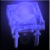
Just started messing with these, and a little disappointed so far, maybe doing something wrong. They do appear brighter at 60 mA than similar 5mm LEDs that I usually use. But not really a big enough difference to justify the higher current, not to mention I have to do PCB artwork in CorelDraw, do to the package and my electronics program doesn't allow me to make parts.

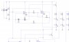
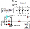
I mount 6 on stripboard, and replaced the 5mms on my fader circuit, got some strange results. The two reds work as expected. Two blues fade in to a point, then sudden full ON bright, fade out very fast. The green similar to the blue. Tried various limiting resistors, same results. Went back to the old 5mms, circuit works, but not the same. Thinking I damaged the LM324s, have to try and replace them.

Also made a growlight (red/blue LEDs), the blue are much brighter then the red, where the 5mms were the other way around.

Now, these are cheap (why I bought them) chinese knockoffs, so there could be some or all defectives. Only burned up one, but was a little rough with soldering iron, oops...

Just wonder what everybody else is experiencing with these LEDs. They were priced about the same as regular LEDs, so too a shot. In practice, seem more trouble then they are worth (probably why they were going so cheap)...
 
Please attach the datasheet for the LEDs and the schematic for your fader.
 
Sorry, could fit the whole schematic on screen and get the parts readable with the screen capture. Yeah, no schematic export as image... But there are two other section, just the same as the first. It's Bill Bowden's 'Fading Red Eyes' times three... I had to adjust the current limiting resistors, but nothing radical.

The "data sheets" are HTML, so here's a link to the website...

**broken link removed**
 

Attachments

  • FaderRGB.jpg
    FaderRGB.jpg
    77.9 KB · Views: 232
The circuit doesn't use enough supply voltage to drive two 3.4V blue or green LEDs in series. Connect a single blue or green LED with a 120 ohm series resistor for a peak current of about 20mA and it should work fine. Then you can add a 2nd blue or green LED with its own 120 ohm resistor to the driver transistor.

The datasheet for the LEDs don't talk about 60mA. Their max is probably only 30mA like all other ordinary LEDs. With a 100 ohm current limiting resistor for two series 2.2V red LEDs, their peak current in this circuit is about only 14mA. 68 ohms would give them a peak current of about 20mA.
 
Yeah the data sheet does give a max current. I looked at the data from some other manufacturers. I got 70mA max DC, and 110ma pulsed. Figured 60mA would be safe enough.

The growlight I made is 2 X 4 blue in series with 1 ohm resistor each row, and one row of 4 red with a 39 ohm resistor. Using a 12 volt 500 mA wallwart for supply. Its on an 8 hour timer, mostly just to supplement light through the window.
 
Finally got around to etching some PCBs this morning. These strips are growlights, using 8 Piranha LEDs, alternating red and blue. The 4 reds, I'm using a 47ohm 1/2 watt, and a 1 ohm 1/4 watt resistor for the blue. Using a 12v 500ma wallwart for supply. No heat issues after 5 hours.

I had a lot of trouble with the reds. Between the two strips I made, had to replace 3. Not sure what went wrong, maybe soldering abuse, but don't think so, least not entirely. Out of 16 LEDS, only screwed up one, three times before getting it right. Guess you can't really complain about chinese quality...

I got the RGB fader back up and running on the regular LEDs. Going to do a 3 Piranha stip board (when I find it, hope I'm not completely out). I've got one section of PCB done. Thought I could just select everything, copy and rotate. Program doesn't do mass rotate. Really hate manuel routing, guess I should just get it over with.

Don't think I'll buy anymore of these LEDs, they just aren't bright enough to justify all the added hassles, and failure rates.

I had hope there would be more post to this thread, but guessing that most people aren't too thrilled with this type of LED either.
 

Attachments

  • LEDstrip.jpg
    LEDstrip.jpg
    14 KB · Views: 179
Never heard of the Piranha Led's, but most normal Led's are rated for 20 mA dc continiously, or in pulse mode up to a max of perhaps 100 mA as long the duty cycle is 1 on, and at least 5 off, for 100 Hz or higher frequency to allowe for the cool down of the Led.

A lot of the high efficiency Led's give already a very bright output at about 3 mA, so that is well below the 20 mA's and will probably result in an unlimited Led life.
 
Piranha is a manufacturer name for a flat, 4 lead package super-flux LED. I got the impression that they would be much brighter than regular LEDs (super bright). Not much info to go on, and just got started messing with them a few weeks ago. At 20 ma, they aren't much different than regular super brights, at 40ma only a little increase, nothing spectacular.

I'm not sure if the ones I got are just bad, or if I'm not using them correctly. They were cheap, so figured I'd give them a try. The data provided was very minimal. Didn't give max current, or any application suggestions or restrictions.

Yesterday, I had to replace one red, three times, before success. I made to PCBs, the first worked fine. The second one kept burning out the same LED. The fourth one worked, hooked both boards up to a 12v 500ma wallwart and ran it for about 8 hours. The transformer got a little warm, not hot enough to get worried about, but should get a bigger one.
 

Attachments

  • SuperFlux-Blue_1_325x325.jpg
    SuperFlux-Blue_1_325x325.jpg
    15.7 KB · Views: 160
If these are the ones I think they are ( I did not look piranah up ), the true brightness comes from their ability to be driven hard at short duty cycle. They are physically made to be able to withstand the thermal cycling that would normally smoke a standard unit.

We use a similar ones at work, but amber, and trust me, when driven to about 75% of their max pulse capability ( around 125mA, very short duration ) it is very uncomfortable to look at on axis.


Do some experimenting and see what the IFP rating is of the piranahs. This is the forward pulse current rating, there will be a duty cycle with this rating. You may be shocked at what these little guys can handle. This is the forward pulse current rating, there will be a duty cycle with this rating. You may be shocked at what these little guys can handle. You can do this pulsing with a very simple CMOS inverter oscillator and a generic to-220 package FET for the drive current. This will dramatically increase the brightness, and also vastly lower the average power consumption of the circuit.
 
Last edited:
The Chinese LEDs that are a copy of Piranha LEDs have a wide angle which reduces their brightness. Some "ultra-bright" LEDs are just an ordinary LED that is focussed into a very narrow angle to look bright on-axis.

I disagree that pulsing an LED makes it appear brighter. Your vision detects the average brightness of a pulsed light, not the peak. That is why multiplexed displays use such a high peak current. Also, many LEDs are less efficient at high current.
A pulse duration of about 20ms or less appears dimmer than the same current for longer duration pulses. Of course your iris reduces the light intensity after a while of continuous light.
 
That is the point. What you do is drive the led as hard as practically possible, allowing for life expectancy, ambient conditions, etc, and by pulsing the drive, you get the brightest average output, while lowering the average power consumption when compared to a steady burn. It is a balancing act, with many variables, not least of which is the human eye-brain perception of what it is seeing or thinks it is seeing.

All those variable message board trailers you see on the highways, contruction or emegency vehicles.... all of the better ones do it this way. Perfect example: a 5 inch LED array used in traffic control, drawing 40ma RMS, and it is visible at 1 KM.

Not trying to argue here, perhaps my previous post was misunderstood.
 
I'll try the PWM. I've got a 555 motor controler on a breadboard some place. It should be good for one LED. Think I had a transistor for the output. Will I still need a series resistor, or is the pulsing good enough to protect the LED?

The lower power consumption is a great plus, my main project for these is an RGB Fader off a solar charged battery. But getting a little concerned about the complexity. Guess I need to figure out a VCO to work with the fader, or maybe its microcontroller time for me.
 
PWM is a dimmer for LEDs as in my Plants Watering Watcher project and in my Ultra-bright Chaser projects.
The lower power consumption is because the average current of the LED and therefore its brightness are less. My Ultra-bright Chaser projects have such a low battery current when the PWM has an extremely narrow pulse (dimmed) that they operate for a very long time on their small battery and don't need an on-off switch.

For your fader project the LEDs must appear continuous and gradually become bright, so PWM won't save much battery power. I have some 3-color faders that operate from a wall-wart adapter.
 
I just hooked up the 555 PWM to 1 blue and 1 red in series. The supply is 6 V 100 ma walwart (voltmeter said 8.5 volts). I left the trimpots at whatever I was running the motor at. There was only a slight flicker, but nice and bright. Adjusted the trimmers, got rid of the flicker, no lose of brightness. Also, adjusted it for a nice strobe effect... Going to let it stobe until I get up for work in about 4 hours, see if it kills the LEDs. Really didn't notice much dimming, just a small range before it flickers. Definately not good for fader, but its a very simplist PWM circuit.

What kind of circuit are you using for your faders? Mine are low freq triangle waves from LM324s.

Oh, the PWM might be good for the growlight project. Haven't done a side by side, but they do look much brighter.
 
HarveyH42 said:
What kind of circuit are you using for your faders?
I use name-brand LEDs and operate them within the ratings on their datasheet.
The dimming circuit is a Cmos Schmitt-trigger oscillator with its duty-cycle changed with a pot and a couple of diodes. It dims from zero to about 98%.
The parts still work when the 3V battery (two AA cells) drops to 2.0V and the current is low because the LEDs each flash very briefly (about 30ms).
 

Attachments

  • LED dimmer.PNG
    LED dimmer.PNG
    38.1 KB · Views: 281
Going to save that, might be useful in the future if need to adust the brightness of one or more LEDS.

The Piranha LEDs I put on the PWM last night were still stobing bright when I got home from work, no fatalities. I have it set for full brightness no flicker right now, and will see how long it lasts. It's about half again as bright as a Piranha on DC through a resistor. Definately worth the added part count, but think you are right in it might not make for a good RGB fader. Later on today, I'm going look for a FET or something that can handle a couple of amps, and drive my growlight strips off it. Going to put those catus in the ground soon, and will start some veggies, with just the LEDs for light. Going to plant the same seeds outside, and see if there is much difference.
 
I am trying a red LED traffic light which got smashed over by a car.
This one has about 200 red LED's on it and just see what happens.
I had to resolder some cracked tracks in the circuitboard and some loose LED's.
Power demand is 19.5 Watts at 230 Volts 50 Hz.
It got a PWM supply board behind the LED's which keeps the current at 80 mA's.
I'm growing cactus, stapelia and mango.
I put this LED light in as addition to the normal fluorescent tubes I have been using for the last 2 years. Also it will compensate for the bluish light output from the fluro's and will give more light from the Red side of the colour spectrum.
 
Hee, hee. We know what you are growing!
Dosn't the growing stop when the red LEDs are lighted??
 
Don't know mate,

Only put the LED light up 4 days ago.

I will see if it works or not :D
 
Status
Not open for further replies.

Latest threads

New Articles From Microcontroller Tips

Back
Top