AllenPitts
Member
Hello ETO forum,
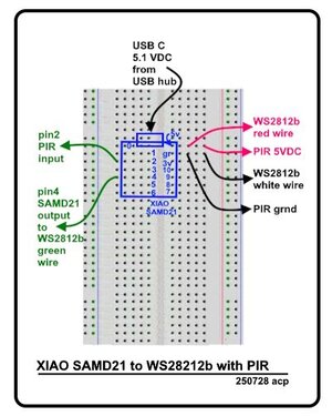
Working with the XIAO SAMD21 to
control addressable LED strip
WS28212b by BTF-Lighting WS2812B SPI RGB LED Strip
SKU: WS2812B5M60LW30.
With a working system it was thought
that it would be good to add a PIR
so the system would light up when approached.
This a pictural of the bread board system built
which works with sketch
PIR_to_SAMD21_to_WS28212b_Fade_Color_250726.ino
herewith attached.
Based on breadboard system operating as
expected, a more permanent circuit was
built using prototype board:

The two-minute video posted shows the
breadboard circuit stays on for about
twenty-six seconds, long enough for
the sketch to pulse the strip four
times. The circuit then glows red
(the last command given by the sketch)
and stays solid red until triggered
by the PIR when the strip begins
the loop by turning blue and repeating
the 26 second cycle.
But the PCB circuit only cycles once
and then glows solid red, also shown
in the video.
The two circuits have been compared
for hours but it cannot be discovered why
the breadboard works as expected and
the PCB does not. Have made several
tests and checked to make sure all
three subsystems, the microcontroller,
the PIR and the LED strip have the
same ground.
Why does the breadboard system work as
expected and the PCB circuit does not?.
Thanks.
Allen Pitts
Working with the XIAO SAMD21 to
control addressable LED strip
WS28212b by BTF-Lighting WS2812B SPI RGB LED Strip
SKU: WS2812B5M60LW30.
With a working system it was thought
that it would be good to add a PIR
so the system would light up when approached.
This a pictural of the bread board system built
which works with sketch
PIR_to_SAMD21_to_WS28212b_Fade_Color_250726.ino
herewith attached.
Based on breadboard system operating as
expected, a more permanent circuit was
built using prototype board:
The two-minute video posted shows the
breadboard circuit stays on for about
twenty-six seconds, long enough for
the sketch to pulse the strip four
times. The circuit then glows red
(the last command given by the sketch)
and stays solid red until triggered
by the PIR when the strip begins
the loop by turning blue and repeating
the 26 second cycle.
But the PCB circuit only cycles once
and then glows solid red, also shown
in the video.
The two circuits have been compared
for hours but it cannot be discovered why
the breadboard works as expected and
the PCB does not. Have made several
tests and checked to make sure all
three subsystems, the microcontroller,
the PIR and the LED strip have the
same ground.
Why does the breadboard system work as
expected and the PCB circuit does not?.
Thanks.
Allen Pitts
Attachments
Last edited:
