Continue to Site

Welcome to our site!

Electro Tech is an online community (with over 170,000 members) who enjoy talking about and building electronic circuits, projects and gadgets. To participate you need to register. Registration is free. Click here to register now.

  • Welcome to our site! Electro Tech is an online community (with over 170,000 members) who enjoy talking about and building electronic circuits, projects and gadgets. To participate you need to register. Registration is free. Click here to register now.

PIR operating a relay

Status
Not open for further replies.

Barmybaz

Member
Help please,
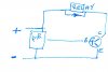
I have several projects that I wish to run from a pir at 6volt, as the projects all tend to run at different voltages I thought operating a relay would be the easiest option, I have available several,
SKU023606 Pirs
BC547 transistors
JQC-3F(T73) relays 3volt, coil resistance of 28Ω (i think)
Various, resisters, Diodes and bits,
Do I have enough bits? do I need more? how do I put them together?
 
hi,
Use your BC547 as a relay driver.
If the PIR output goes high on detect, say ~5V, the use a series resistor to the Base of the BC547.
Add a diode across the relay coil.
E
 
hi,
Use your BC547 as a relay driver.
If the PIR output goes high on detect, say ~5V, the use a series resistor to the Base of the BC547.
Add a diode across the relay coil.
E

I just spoke to the OP and learned he used to be an assembler. I think he could work from a schematic but may not be able to get how things work together?

Barmybaz, sorry I didn't mean to be "rude" when I changed the subject in "Chat" I don't have much time today and needed a Math question answered.

Good luck with your project. Eric, will get you straightened out.

kv
 
Hi
thanks for your advice, kv is right about a schematic, just to be sure, is this the circuit you are suggesting,
Its just that I'm a pensioner looking for a hobby, not very good yet.
no prob' kv
 

Attachments

  • pir relay drive circuit.jpg
    pir relay drive circuit.jpg
    86.3 KB · Views: 289
Hi
thanks for your advice, kv is right about a schematic, just to be sure, is this the circuit you are suggesting,
Its just that I'm a pensioner looking for a hobby, not very good yet.
no prob' kv

As he suggested you'll need a resistor on the base of the Transistor; not to sure what the value would be. The Diode looks correct.

kv

Edit: I spotted a 10k on the base of several circuits using a uC. Which most likely is between 2 and 5v. Should work; but then I'm not an Engineer.
 
Last edited:
hi Barmy,
Post details of the PIR output signal, ie: Low /High voltage and type number if you have it.
E
 
Hi Eric
The output of the p,i,r is quoted at 3v.
going to put it together today, (what could possibly go wrong, :) lol)
 
hi Barmy,
Add a series resistor between the 3V output of the PIR and the transistor Base, say 330R.
Do you want a diagram.?
E
 
Eventually got to wire it up today, BRILLIANT ! EXCELLENT !
Now my cat repellent, (solar powered). grandchildrens fairy house, (night light) and light house (garden light) are all a reality.
can't thank you both enough for your help.
One point, I had to take out the diode, (one I found in box of bits, could have been faulty) does this matter, if so can you suggest a replacment,
Thank you both again.

Barmy
 
One point, I had to take out the diode,
Hi,
A suppression diode across the relay coil is essential, cathode to supply voltage, anode to transistor collector.
E
 
Status
Not open for further replies.

Latest threads

Back
Top