ZERS
New Member
Hi all,
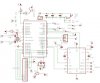
I was wondering if the attached schematic is correct to program th e PIC18F452 'in situ'.
I've got a PIC programmer but I want to be able to re-program the PIC when it will be in position into my CD player.
The "programming" circuit is made of :
1-MAX232 to connect the DB9F cable, coming from my PC
2- The max232A is linked to the pic as follows :
- TX to RC6 (pin 26 of the PIC)
- RX to RC7 (pin 27) and RB6 (pin 39)
Is it correct ?
regards