Continue to Site

Welcome to our site!

Electro Tech is an online community (with over 170,000 members) who enjoy talking about and building electronic circuits, projects and gadgets. To participate you need to register. Registration is free. Click here to register now.

  • Welcome to our site! Electro Tech is an online community (with over 170,000 members) who enjoy talking about and building electronic circuits, projects and gadgets. To participate you need to register. Registration is free. Click here to register now.

PID Calculations - have I got it right?

Status
Not open for further replies.

ACharnley

Member
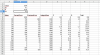
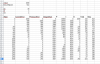
I've wrote a simple PID controller routine (below). I haven't tested it yet (float's will need working to ints etc) but I was hoping to model it first and to that end I've created a spreadsheet which is attached.

I've noticed that the output is always positive, so even when there's no error the output is about +24 on the duty cycle. This seems to be related to the integralTotal which will only decay when the output has a positive error. All help appreciated!

Code:
float p_gain = 0.01;
float i_gain = 0.01;
float d_gain = 0.00;

int16_t PID (int16_t currentError, int16_t *previousError, uint8_t *integral) {
    int16_t output = (p_gain * currentError) + (*integral * i_gain) + (d_gain * (currentError - *previousError));
    *integral = *integral + currentError;
    *previousError = currentError;
    return output;
}
 

Attachments

  • PDI.ods.zip
    9.8 KB · Views: 130
I think you need to wrap it in a closed loop system to get practical results.

Try adding external values for a target value and the "thing" being controlled. Update the control value by subtracting a proportion of the algorithm output, then feed the target-control error back as the input.

It should settle.

You could add a random offset to the target setting every few hundred passes, to see how well it tracks.
 
I take it you mean entering the formulae in software that can model the output feeding back into the input? Any recommendations?

Looking at my spreadsheet, you can see that 280 and 282 are interesting in that the duty has actually dropped. At 290 it does rise again but I would have thought the duty would have been higher between 280 and 282 than 282 and 290 and certainly not negative.

One more query, if the error is negative (so above ideal voltage level) then the duty goes negative. Originally I thought it was new duty = old duty + PID output, but I read elsewhere this is not the case (being as my ADC and PWM are both 10 bit I can directly use the PID output as the PWM duty value). If it's used directly how do the negatives work?
 

Attachments

  • Screenshot_2019-03-07_12-05-53.png
    Screenshot_2019-03-07_12-05-53.png
    37.2 KB · Views: 148
From the spreadsheet image, it looks to be working reasonably well, just needing the gain parameters tweaking a bit to optimise it.

For something like PWM, work with a signed output then add half the PWM max; eg. if it were 10 bit, 0-1024, calculate it with output range of + / - 512 then add 512 to that as it's passed to the PWM.

It would probably also need limiting so if it's less than -512 or greater than +512 it's set to the appropriate limit.
 
Here's the final algorithm. It assumes your duty can go from 0 - 100% and is 10 bit.

Code:
uint16_t PID (int16_t currentError, int16_t *previousError, int16_t *integral, uint8_t pGain, uint8_t iGain, uint8_t dGain) {
    
    // proportional
    int24_t output = pGain * currentError;

    // integral
    output += iGain * *integral;

    // differential
    output += dGain * (currentError - *previousError);
    
    // adjust for int gains    
    output = output / 100;
    
    // add midpoint
    output += 512;
    
    // no negatives
    if (output < 0) {
        output = 0;
    }
    
    // limit to 10 bit
    output &= 1023;
   
    // saves
    *integral = *integral + currentError;
    *previousError = currentError;
    
    return (uint16_t) output;
}

I've tweaked the spreadsheet so that the values are more reasonable. My understanding is:

pGain appears to be how aggressive it is (a large error equates to a larger value),

iGain effects the delta over time (that is, if a change doesn't correct the error then the integral becomes a greater part of the correction)

dGain settles/damps the error correction.
 

Attachments

  • pdi.png
    pdi.png
    59.9 KB · Views: 142
  • PDI.ods.zip
    11.8 KB · Views: 133
Status
Not open for further replies.

Latest threads

New Articles From Microcontroller Tips

Back
Top