Hello guys.
We are two students that are doing a project*. We have posted a few posts here earlier, and got a lot of help.
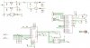
Now we are almost done with the circuit, and wondering if some of you can have a look at it and give us some feedback and/or comments.
We have also a few questions about some pins on the pvp9390 (picture in picture IC.)
Pin 6, SEL - Fast blanking output for PIP, black screen out? cvbs?
Pin 38, INTR - Interrupt output
Pin 41, VSP - Vertical sync for parent channel
Pin 42, HSP - Horizontal sync for parent channel this is input signals, The camera we are using gives out CVBS, does this signal contain the V/H sync signal?
I know, there are alot of questions")
Thanks for any feedback!
* The project it to connect two cameras and look at them at one tv screen.
Like this
I`m also adding the PVP9390 datasheet if any of you want to see it (1.4 MB) **broken link removed** the pin description are on page 91
NB: I also added the schamatic for the circuit, it`s in eagle, rename the *.asc to *.sch if you wanna look at it..
We are two students that are doing a project*. We have posted a few posts here earlier, and got a lot of help.
Now we are almost done with the circuit, and wondering if some of you can have a look at it and give us some feedback and/or comments.
We have also a few questions about some pins on the pvp9390 (picture in picture IC.)
Pin 6, SEL - Fast blanking output for PIP, black screen out? cvbs?
Pin 38, INTR - Interrupt output
Pin 41, VSP - Vertical sync for parent channel
Pin 42, HSP - Horizontal sync for parent channel this is input signals, The camera we are using gives out CVBS, does this signal contain the V/H sync signal?
I know, there are alot of questions
Thanks for any feedback!
* The project it to connect two cameras and look at them at one tv screen.
Like this
I`m also adding the PVP9390 datasheet if any of you want to see it (1.4 MB) **broken link removed** the pin description are on page 91
NB: I also added the schamatic for the circuit, it`s in eagle, rename the *.asc to *.sch if you wanna look at it..