Continue to Site

Welcome to our site!

Electro Tech is an online community (with over 170,000 members) who enjoy talking about and building electronic circuits, projects and gadgets. To participate you need to register. Registration is free. Click here to register now.

  • Welcome to our site! Electro Tech is an online community (with over 170,000 members) who enjoy talking about and building electronic circuits, projects and gadgets. To participate you need to register. Registration is free. Click here to register now.

PIC16F887 and Anti-Aliasing..

Status
Not open for further replies.

@m@

New Member
hello dear friends..
I am working on PIC16F887 , when i applied AC signal to its ADC input pin then it is not giving a correct conversion for sine wave ...
So how to select best sampling rate for A/d conversion .. ?
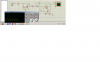
here is my code I changed and implement different values of ADCON0 but no use...
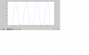
Code:
unsigned int temp_res;
 char buf2[6];
 int i;
void main() {
  UART1_Init(9600);
  ADCON1 = 0x80;
  ADCON0=0xC1;
  TRISA  = 0xFF;
  ANSEL  = 0xFF;              // Configure AN2 pin as analog
  //ANSELH = 0;                 // Configure other AN pins as digital I/O
  C1ON_bit = 0;               // Disable comparators
  C2ON_bit = 0;

  TRISA  = 0xFF;              // PORTA is input
  TRISC  = 0;                 // PORTC is output
  TRISB  = 0;                 // PORTB is output

  do {
    temp_res = ADC_Read(0);   // Get 10-bit results of AD conversion
    PORTB = temp_res;         // Send lower 8 bits to PORTB
    PORTC = temp_res >> 8;    // Send 2 most significant bits to RC1, RC0
  wordToStr(temp_res,buf2);

    for(i = 0; i < 6; i++)
    {
      UART1_Write(buf2[i]);
      Delay_ms(80);
      }} while(1);
      }
here is my aliased sine wave :( is attached
I have already pass my signal through clamper and then anti-aliasing filter..
But what i think so that problem is with MCU frequency clock ..When I changes it to 150 Mhz:confused: so signals becomes much better but it is too high ..
Please guide...
 

Attachments

  • aliased.png
    aliased.png
    45.1 KB · Views: 245
hi,
What range of input frequencies are you working with.??

Also can you post a diagram for clamp and anti alias filter.?
 
Last edited:
Do you realise that you are only reading 10 samples per second? If you are sampling 50Hz then you need to be reading the ADC at a much higher rate.

Edit, just looked at your code again and you're reading at about 2 samples per second.

Mike.
 
Last edited:
Yes.. I know that there is problem with my code especially when Input is AC signal because this code works fine for DC input voltages...
I am newbie to PIC and and made this program with the help of different examples and data sheet .. So please could u guide that which code lines should be edited for my sampling ..
I put and change values in ADCON0 register but not change :( ..
Please guide... thank u ...
 
Assuming you don't need to sample continuously, I would sample into a buffer and then send to the PC. Your attachment above suggests you are sampling a 5Hz wave form, is that correct? Which compiler are you using and can you post a compilable version of your code. I ask as at the moment I have no idea whether you are using library functions or not and what they do.

Mike.
 
I am using the MiKroC compiler..
Yes in the above attachment i was sampling 5Hz sine wave..
I edited this code using the example available in MikroC for ADC and UART...
 
I don't use MikroC and so I don't know what there libraries do. However, to get higher res just change the delay and see how that works out.
Code:
  do {
    temp_res = ADC_Read(0);   // Get 10-bit results of AD conversion
    PORTB = temp_res;         // Send lower 8 bits to PORTB
    PORTC = temp_res >> 8;    // Send 2 most significant bits to RC1, RC0
    wordToStr(temp_res,buf2);
 
    for(i = 0; i < 6; i++)
    {
      UART1_Write(buf2[i]);
      Delay_ms(2);
     }
  } while(1);
}

This should allow about 60 to 70 samples per second.

Edit, looks like the board is broke again and not showing colours. In the above I changed the delay to 2mS.

Mike.
 
Last edited:
hmmm, Something different but it is not sine.. huh.. .. :(
 

Attachments

  • aliased.png
    aliased.png
    108.6 KB · Views: 235
That is a very clipped waveform. It looks like the AC that you are feeding the chip is greater than 5V.

Mike.
 
Last edited:
okay,, Thanks Alot... See my waveform I think it is good now... ? :D
But i think it is still not clamping correctly ..
 

Attachments

  • aliased.png
    aliased.png
    79.3 KB · Views: 222
Now, I just changed the clamping circuit...:)
Input is 2.4 V Amplitude Sinewave
 

Attachments

  • aliased.png
    aliased.png
    91.7 KB · Views: 225
Status
Not open for further replies.

New Articles From Microcontroller Tips

Back
Top