Hello everyone, I am rather new to programming and wanting to get general help.
The aim of my project is to make a Dual H - Bridge motor controller CODE with a L293Chip. Which is going to be used to control a "Aqua Drone" on the water. There will be 2 motors, which spin together, or individually depending which direction is chosen to go ( left motor spins = turns right , right motor spins = turns left , both motors spin = straight). For now only those 3 functions are needed to work ( im aware that you can also make them spin in different directions).
Electronically, i have connected everything for the L293, even made my own 433Mhz Wireless controllers to activate the motors (using the activation pins). The circuit works with the mechanic/electronic activation , however i am wanting to include a PIC16F877A chip to do the logic of activating the L293 chip and its motors for personal development.
Basic action i am wanting the PIC16877a to do (mplab 8.70), is to first recognize the wireless receivers inputs to the PIC (from the transmitter on the remote control, https://www.globalsources.com/gsol/I/RF-module/p/sm/1108582354.htm#1108582354 ). Once those inputs are activated on the PIC , using IF statements (and other? ) in the code - 2 out puts can be activated 1 at a time ( or 2 at a time in order to get both motors spinning.) So this will need 2 bits of code, assuming both the inputs can be held high at the same time to get both outputs going (ultimately powering on both motors at the same time). Those 2 PIC outputs would be connected to the L293 activation pins (any of the 2 from - pin 2 , 7, 15 or 10 ), so for example R01 is pressed the output will be R05 ( i dont know that the output pins could be ) so the left motor spins, when R02 is pressed the R04 goes high and the right motor spins, when both R01 and R02 are pressed then R04 and R05 are both active giving signal for both motors to spin.
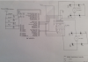
ATTACHED FILE - The diagram presents a concept of how it could work , but ive decided not to use the PWM method as there is no need, so just left right and both at the same time method is fine ( as long as it spins ! haha ) . The digram presents simple function of how PWM is desired to work but i think that would be too much for me at this stage !
So yes, i want either 1 output or 2 outputs at the same time going in order to get the motors spinning to steer the Aqua Drone (boat) into desired direction.
I am no longer at Uni, graduating on the 16th. Unfortunately my course wasnt offering many programming papers and i just didnt have enough time to learn C++. Just wanting to complete this little Aquad Drone. Any help, such as related parts that could be used would be helpful. I know this is really easy to do, however i just dont know where to start! IF this is the wrong forum and you know any other forums which could help me better please let me know! Any help is highly appreciated.
Kind Regards
The aim of my project is to make a Dual H - Bridge motor controller CODE with a L293Chip. Which is going to be used to control a "Aqua Drone" on the water. There will be 2 motors, which spin together, or individually depending which direction is chosen to go ( left motor spins = turns right , right motor spins = turns left , both motors spin = straight). For now only those 3 functions are needed to work ( im aware that you can also make them spin in different directions).
Electronically, i have connected everything for the L293, even made my own 433Mhz Wireless controllers to activate the motors (using the activation pins). The circuit works with the mechanic/electronic activation , however i am wanting to include a PIC16F877A chip to do the logic of activating the L293 chip and its motors for personal development.
Basic action i am wanting the PIC16877a to do (mplab 8.70), is to first recognize the wireless receivers inputs to the PIC (from the transmitter on the remote control, https://www.globalsources.com/gsol/I/RF-module/p/sm/1108582354.htm#1108582354 ). Once those inputs are activated on the PIC , using IF statements (and other? ) in the code - 2 out puts can be activated 1 at a time ( or 2 at a time in order to get both motors spinning.) So this will need 2 bits of code, assuming both the inputs can be held high at the same time to get both outputs going (ultimately powering on both motors at the same time). Those 2 PIC outputs would be connected to the L293 activation pins (any of the 2 from - pin 2 , 7, 15 or 10 ), so for example R01 is pressed the output will be R05 ( i dont know that the output pins could be ) so the left motor spins, when R02 is pressed the R04 goes high and the right motor spins, when both R01 and R02 are pressed then R04 and R05 are both active giving signal for both motors to spin.
ATTACHED FILE - The diagram presents a concept of how it could work , but ive decided not to use the PWM method as there is no need, so just left right and both at the same time method is fine ( as long as it spins ! haha ) . The digram presents simple function of how PWM is desired to work but i think that would be too much for me at this stage !
So yes, i want either 1 output or 2 outputs at the same time going in order to get the motors spinning to steer the Aqua Drone (boat) into desired direction.
I am no longer at Uni, graduating on the 16th. Unfortunately my course wasnt offering many programming papers and i just didnt have enough time to learn C++. Just wanting to complete this little Aquad Drone. Any help, such as related parts that could be used would be helpful. I know this is really easy to do, however i just dont know where to start! IF this is the wrong forum and you know any other forums which could help me better please let me know! Any help is highly appreciated.
Kind Regards