Electro Tech is an online community (with over 170,000 members) who enjoy talking about and building electronic circuits, projects and gadgets. To participate you need to register. Registration is free. Click here to register now.
Welcome to our site! Electro Tech is an online community (with over 170,000 members) who enjoy talking about and building electronic circuits, projects and gadgets. To participate you need to register. Registration is free. Click here to register now.
hi Hesham,
I explained days ago how the PIC generates an Interrupt.
You write the appropriate bits into the Control registers for the Internal PIC peripheral that you want to generate the Interrupt.
So when the condition within the peripheral is met, IT generates the Interrupt.
If you wanted say Timer 1 to generate an interrupt on Overflow you would set the correct bits in the Timer 1 Control registers.
So when the program start running the Timer 1 will run independant from the program right?
Then, When an overflow happen say after 2ms for an On time the timer start again from begining and another overflow happen say after 18ms for an Off time the timer start again and again right?
So when the program start running the Timer 1 will run independant from the program right?
Then, When an overflow happen say after 2ms for an On time the timer start again from begining and another overflow happen say after 18ms for an Off time the timer start again and again right?
If you read the data sheet and specifically the PWM section, you will find an explanation of the special event trigger(SET). When the PWM module is setup to use the SET, the CCP1L/H registers effectively become the time period for timer 1. Whatever value is written to CCP1L/H will be the value that timer 1 resets at and also causes an interrupt. Study the code and see how that happens.
Also, read the data sheet and try to figure out what the (my) code is actually doing rather than just keep asking newby questions here. You have been a member here for over 9 months and you are still asking basic questions.
Ya, Reading and asking newby questions are improper thing to do I totally agree.
Maybe I keep asking dumpy questions because I think its hard one but when you answer them it appear to be easy.
I will try my best googling before asking any new newby question.
I think knowing how to activate a timer using MPLAB to see the REAL TIME of a program is an essential thing to learn so you can test your code prior programming and using function generator.
Q1> How can i activate the timer in simulation in MPLAB assembly? If this is a simple question ignore it if you think it will help many people answer it
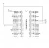
I have a servo motor ds8911 which need a voltage between 4.8-7.4V. I am using 5V from the same power supply to the PIC and the servo and also I am using same ground as for the PIC and as for the servo. The control wire of the servo is connected to RB0.
I have a servo motor ds8911 which need a voltage between 4.8-7.4V. I am using 5V from the same power supply to the PIC and the servo and also I am using same ground as for the PIC and as for the servo. The control wire of the servo is connected to RB0.
How is the servo motor connected to the PIC pin, is the PIC capable of driving that servo directly or will it require a transistor driver.?
EDIT: attached a spec for the motor NOTE the drive current.!!!
hi,
The Control wire is most likely a TTL voltage level, I cannot see any reference in the spec sheet.
I was concerned that you may have been trying to connect the motor directly to the PIC.!
If possible, its a good idea to have a separate power supply to the motor, it can draw over 2.7Amps from the 5V line.
What is the voltage source for the project.?
Right now I am using 5V power supply of our LAB it can handle heavy current like 20A in the future I am thinking about using small AA size batteries connect many in parrallel.
The servo motor is not connect to anything right now I am doing a free test.
Can some one comment on my previous post servo motor diagram why it's not working?
I already connected an Oscilloscope to RB0 and tried reading the generated pulse nothing was showing>< Any Ideas?
This site uses cookies to help personalise content, tailor your experience and to keep you logged in if you register.
By continuing to use this site, you are consenting to our use of cookies.