Continue to Site

Welcome to our site!

Electro Tech is an online community (with over 170,000 members) who enjoy talking about and building electronic circuits, projects and gadgets. To participate you need to register. Registration is free. Click here to register now.

  • Welcome to our site! Electro Tech is an online community (with over 170,000 members) who enjoy talking about and building electronic circuits, projects and gadgets. To participate you need to register. Registration is free. Click here to register now.

PIC timer problem

Status
Not open for further replies.

ljcox

Well-Known Member
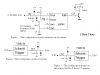
I wrote a programme for a 16F84 PIC to operate a relay for 1 hour as in Figure 1. But the results depend upon what signal is input to RA4.

If a sinewave of 50Hz is input, as in Figure 1, it works sometimes but not always.

If a slope limited squarewave signal is input, as in Figure 2, it works everytime.

If a pure squarewave signal is input, as in Figure 3, it works but the delay is 2 hours 1.5 minutes - obviously slightly more than half the pulses input to RA4 are missed.

Does anyone know why?

According to the PIC data sheet, RA4 has a Schmitt Trigger input, so the input wave shape should not be relevant - provided it is large enough in amplitude to cross the upper and lower thresholds.

Len
 

Attachments

  • 50hztimer_1.png
    50hztimer_1.png
    4.2 KB · Views: 1,117
I suspect noise on your 5V line maybe the problem. Your AC will drive your 5V line higher than 5V and may mess up your other RC oscillator - especially if your circuit has a low standby current. Try putting a 5V zener across your capacitor instead of the diode to 5V.

Mike.
 
Why don't you use a 3.2768 MHz (or 32.768 kHz) crystal oscillator?
3276800 Hz=4(TIMER0 runs at CLK/4) * 256(TIMER0 Overflow) * 128 (TIMER0 Prescaler) * 25(At 25 TIMER0 Interrupts you have 1 second).
 
Pommie said:
I suspect noise on your 5V line maybe the problem. Your AC will drive your 5V line higher than 5V and may mess up your other RC oscillator - especially if your circuit has a low standby current. Try putting a 5V zener across your capacitor instead of the diode to 5V.

Mike.

Thanks for the comment Mike, but I would have thought that the current through the 100 k resistor into the diode would be small enough to not cause a problem. Besides, I would like to know why this is happening.

Yes, Alex.m, a crystal is a possible solution, I used a RC oscillator for simplicity - it seems silly to have the PIC running at 3 odd MHz when the output is in hours.

Perhaps a 32 kHz crystal would be a good compromise.

Len
 
50hz

hi
is your 50hz signal 240ac mains?
if so it is most likely mains spikes from things switching on or off,
resetting your pic.


phill
 
Hi Len

intriguing problem...

Your fig 2, shows a schmitt trigger whose output goes from 0v to some positive value and this one works. The other figs have a 0v level determined by the catching diode. I don't know why you have the 27n capacitor in circuit?, it has a reactance of ~120K at 50Hz and time constant of ~2ms (Fully charged in 5CR = 10ms, suspicious ) :eek: . Short answer is I don't know but I'm going to look into it when I get a mo.

Best of Luck

Ed
 
time/power

use a 455khz crystal for low power or
to save more power use the watchdog timer to wake pic from sleep
add that time to a reg go back to sleep till you have 1 hour.
phill
 
EdwardM said:
Your fig 2, shows a schmitt trigger whose output goes from 0v to some positive value and this one works. The other figs have a 0v level determined by the catching diode. I don't know why you have the 27n capacitor in circuit?, it has a reactance of ~120K at 50Hz and time constant of ~2ms (Fully charged in 5CR = 10ms, suspicious ) :eek: . Short answer is I don't know but I'm going to look into it when I get a mo.

Ed

Ed, the reason for the 100k and 27 nF is to act as a low pass filter to hopefully remove the spikes from the AC mains that Phill mentioned.
I'm keen to hear your conclusions.

The 3 dB point is given by F = 1/(2Pi RC) = about 60 Hz.

Thank you all for the help so far, I don't want to resort to a crystal yet (even though it would be cleaner), I want to determine what the problem is as it has me intrigued.

Len
 
ljcox said:
Ed, the reason for the 100k and 27 nF is to act as a low pass filter to hopefully remove the spikes from the AC mains that Phill mentioned.
I'm keen to hear your conclusions.

The 3 dB point is given by F = 1/(2Pi RC) = about 60 Hz.

Thank you all for the help so far, I don't want to resort to a crystal yet (even though it would be cleaner), I want to determine what the problem is as it has me intrigued.

The whole idea of this is to get reliable SQUARE pulses entering the PIC, by adding such a low frequency low-pass filter you will be making the drive nearer a sinewave than a square wave.

So dump the capacitor!, also dump the two diodes, they aren't required, the PIC already has them internally - see figure 5.4 of the 16F628 datasheet.
 
Hi Len

I've built your fig 1, minus the PIC (New computer, PIC stuff not installed yet) and haven't really found any reason why it shouldn't work - the only thing I can think of is that maybe the diode to +5v is high resistance this would mean that the max input voltage to RA4 (8.5v) could be exceeded, however as Nigel correctly says diodes are already built into RA4 to Vdd and Vss and this would mean that that upper PIC diode was faulty too! (cyclic latchup?, clutching at straws here, if that is a problem then new diode and PIC would solve it).

T'other thing is I've tried it with both silicon and schottky diodes, not that it should matter much, and it looks like you may be exceeding the abs max ratings for RA4 (>-0.3V wrt Vss).

On the 'scope the waveform looks OK, ie a phase shifted slowish slope waveform and with the 0.1v hysteresis buit in to RA4 that shouldn't be a prob.

Don't you just hate it when you can't find the answer :oops:

Best of Luck

Ed
 
EdwardM said:
T'other thing is I've tried it with both silicon and schottky diodes, not that it should matter much, and it looks like you may be exceeding the abs max ratings for RA4 (>-0.3V wrt Vss).

The PIC is quite happy with any voltage fed through a suitable current limiting resistor directly into the pin, the internal diodes clamp the voltage to the supply rails. Many of the MicroChip application notes show just that, including a simple resistor direct from the mains for zero-crossing detection.

The MAX voltage rating applies to a voltage source with no current limiting, when it's ESSENTIAL that the internal diodes don't conduct - which would probably cook the chip, or as a minimum kill that I/O pin.
 
Nigel Goodwin said:
The PIC is quite happy with any voltage fed through a suitable current limiting resistor directly into the pin, the internal diodes clamp the voltage to the supply rails. Many of the MicroChip application notes show just that, including a simple resistor direct from the mains for zero-crossing detection.

This depends on the current sinking abilities of the reg and the current consumption on the +5v bus. It is very possible to cause latchup under certain circumstances.

Say the PIC is asleep and drawing negligible current, and nothing else on the +5v bus draws current. You put 20mA through that pin to the +5v rail. Anything greater than the reg can sink will charge the Vdd cap and this can increase Vdd until it exceeds latchup voltage. It won't matter if he uses an external diode or the PIC pin protection diode. A 5.1v zener would do the job if you can guarantee the reg and zener tolerances won't overlap.

Reg mfgs are often vague on the sink capabilities. Looking at a TI uA7805 spec I pulled out, they don't list it and the current path from the diagram is so convoluted I'm not sure it can sink anything substantial or not.

But 100k would be a pretty small current. In fact, 120 uA is low enough that he might want to look into whether the pin's internal leakage current may be interfering with the voltage seen on the pin.
 
Nigel Goodwin said:
The whole idea of this is to get reliable SQUARE pulses entering the PIC, by adding such a low frequency low-pass filter you will be making the drive nearer a sinewave than a square wave.

So dump the capacitor!, also dump the two diodes, they aren't required, the PIC already has them internally - see figure 5.4 of the 16F628 datasheet.

Nigel,
Thanks for response. But if you look at my Figure 3, it is being presented with a squarewave but will not work. The only config that does work reliably is Figure 2 - a non square wave. ?? I know the PIC has internal diodes, but I was once told by an IC researcher (admittedly a few decades ago) that the internal diodes are sometimes not adequate.

The PIC data sheet for the 16F84 states that RA4 has an internal Schmitt Trigger, so it sould work on slow waveforms - as we found. My main question is - why is it having a problem with the square wave as per fig 3?

The RC filter is to attenuate any spikes from the mains.

Len
 
EdwardM said:
T'other thing is I've tried it with both silicon and schottky diodes, not that it should matter much, and it looks like you may be exceeding the abs max ratings for RA4 (>-0.3V wrt Vss).

Don't you just hate it when you can't find the answer

Best of Luck

Ed
Thanks Ed, but, as Nigel said, the -0.3 V max should not be an issue since the input is current limited by the 100k.

Yes

Len
 
Oznog said:
This depends on the current sinking abilities of the reg and the current consumption on the +5v bus. It is very possible to cause latchup under certain circumstances.

Say the PIC is asleep and drawing negligible current, and nothing else on the +5v bus draws current. You put 20mA through that pin to the +5v rail. Anything greater than the reg can sink will charge the Vdd cap and this can increase Vdd until it exceeds latchup voltage. It won't matter if he uses an external diode or the PIC pin protection diode. A 5.1v zener would do the job if you can guarantee the reg and zener tolerances won't overlap.

Reg mfgs are often vague on the sink capabilities. Looking at a TI uA7805 spec I pulled out, they don't list it and the current path from the diagram is so convoluted I'm not sure it can sink anything substantial or not.

But 100k would be a pretty small current. In fact, 120 uA is low enough that he might want to look into whether the pin's internal leakage current may be interfering with the voltage seen on the pin.

Thanks for the response Oznog,
1. I expect the current consumption on the +5V is greater than the small current through the 100k, but I check it.

2. the PIC is not in sleep. 5V1 Zeners have a fairly rounded "knee" so I suspect it will "absorb" the current from the 100k before it reaches 5V.

3. to prove this point we can load the +5V with say a 10 mA dummy.

4. I had not thought about the internal leakage current but feel that it would be in the nA region and thus swamped by the resistor current. I'll check the spec.

Len
 
ljcox said:
Nigel Goodwin said:
The whole idea of this is to get reliable SQUARE pulses entering the PIC, by adding such a low frequency low-pass filter you will be making the drive nearer a sinewave than a square wave.

So dump the capacitor!, also dump the two diodes, they aren't required, the PIC already has them internally - see figure 5.4 of the 16F628 datasheet.

Nigel,
Thanks for response. But if you look at my Figure 3, it is being presented with a squarewave but will not work. The only config that does work reliably is Figure 2 - a non square wave. ?? I know the PIC has internal diodes, but I was once told by an IC researcher (admittedly a few decades ago) that the internal diodes are sometimes not adequate.

The PIC data sheet for the 16F84 states that RA4 has an internal Schmitt Trigger, so it sould work on slow waveforms - as we found. My main question is - why is it having a problem with the square wave as per fig 3?

Obviously the input to the PIC is different in fig 3, or it wouldn't have any effect, have you tried scoping the RA4 pin to see what the waveform is like?. For that matter have you tried a plain 100K feeding the pin, and nothing else?.
 
Hi Len,

Can you do a test by increasing the clock speed of the PIC to 100KHz or higher and see if the problem remains?
 
Status
Not open for further replies.

Latest threads

New Articles From Microcontroller Tips

Back
Top