Continue to Site

Welcome to our site!

Electro Tech is an online community (with over 170,000 members) who enjoy talking about and building electronic circuits, projects and gadgets. To participate you need to register. Registration is free. Click here to register now.

  • Welcome to our site! Electro Tech is an online community (with over 170,000 members) who enjoy talking about and building electronic circuits, projects and gadgets. To participate you need to register. Registration is free. Click here to register now.

PIC test board

Status
Not open for further replies.

MrDEB

Well-Known Member
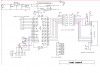
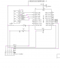
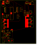
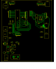
Here is the PIC test board or protype test board.
Has a spdt selector switch to select either the 40 pin or 18 pin socket with indicator LEDs
lots of daughter board connections and LCD headers (don't have to rewire everytime I want to run an LCD program (need to redo code for the 18F1320)
Got the idea from **broken link removed**
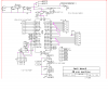
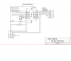
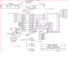
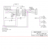
the board streamlines the rewiring of parts for a breadboard. Also frees up breadboard space.
**broken link removed**
 
Dear nice effort. But where is the schematic you used and backside picture of the board for the board readers to evaluate your efforts
 
Will post updated pics of schematic.
backside is not real pretty as it is all point to point hard wiring using wire wrap wire.
 
test board to date

here is a schematic of what I have so far. Thinking about etching a board to eliminate alot of "wire traffic" which adds to the confussion.
 

Attachments

  • test board 4_1_10&#11.PNG
    test board 4_1_10&#11.PNG
    46.2 KB · Views: 389
  • test board 4_1_10&#11.PNG
    test board 4_1_10&#11.PNG
    24 KB · Views: 311
Looking at that schematic, you seem to have an LED (D1) that tells you when it's off!

Mike.
 
D1 and D3 are both connected to the selector switch. When selected the LED comes on.
I have an updated schematic and then on to a pc board.
 

Attachments

  • testboard2-1..PNG
    testboard2-1..PNG
    40.3 KB · Views: 261
  • testboard2-2..PNG
    testboard2-2..PNG
    27.2 KB · Views: 232
here is the START of PCboard

not real small 5x7"
has on board power supply.
This is for a two layer board with all grounds, Vccicsp, crystals on top layer (should make registration easier?
All ports on bottom layer.
 

Attachments

  • testboard pcb pwr.PNG
    testboard pcb pwr.PNG
    33.4 KB · Views: 251
bottom layer of pc board

this pcboard has yet to be doubled checked but there really isn't much to look at,
ALL the ports are connected using the bottom layer.
NOTE I changed a few headers.
 

Attachments

  • testboard data..PNG
    testboard data..PNG
    28.5 KB · Views: 254
updated test board schematics

added an LCD port to the 40 pin section, several logic buttons.
I have express pcb files if anyone interested.
This board should save lots of bread board repetitive circuits.
ANY addition suggestions welcome
 

Attachments

  • testboard2-1..PNG
    testboard2-1..PNG
    42.4 KB · Views: 227
  • testboard2-2..PNG
    testboard2-2..PNG
    26.5 KB · Views: 224
Status
Not open for further replies.

New Articles From Microcontroller Tips

Back
Top