Continue to Site

Welcome to our site!

Electro Tech is an online community (with over 170,000 members) who enjoy talking about and building electronic circuits, projects and gadgets. To participate you need to register. Registration is free. Click here to register now.

  • Welcome to our site! Electro Tech is an online community (with over 170,000 members) who enjoy talking about and building electronic circuits, projects and gadgets. To participate you need to register. Registration is free. Click here to register now.

PIC Program Understanding?

Status
Not open for further replies.

Wond3rboy

Member
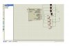
Hi i am a starter at PIC just reached the second tutorial from Nigels site.Here is the problem.

Code:
;Tutorial 2.2 - Nigel Goodwin 2002
	LIST	p=16F628		;tell assembler what chip we are using
	include "P16F628.inc"		;include the defaults for the chip
	__config 0x3D18			;sets the configuration settings (oscillator type etc.)

	cblock 	0x20 			;start of general purpose registers
		count1 			;used in delay routine
		counta 			;used in delay routine 
		countb 			;used in delay routine
	endc

LEDPORT	Equ	PORTA			;set constant LEDPORT = 'PORTA'
SWPORT	Equ	PORTA			;set constant SWPORT = 'PORTA'
LEDTRIS	Equ	TRISA			;set constant for TRIS register
SW1	Equ	7			;set constants for the switches
SW2	Equ	6
SW3	Equ	5
SW4	Equ	4
LED1	Equ	3			;and for the LED's
LED2	Equ	2
LED3	Equ	1
LED4	Equ	0

SWDel	Set	Del50			;set the de-bounce delay (has to use 'Set' and not 'Equ')

;end of defines
	
	org	0x0000			;org sets the origin, 0x0000 for the 16F628,
					;this is where the program starts running	
	movlw	0x07
	movwf	CMCON			;turn comparators off (make it like a 16F84)

   	bsf 	STATUS,		RP0	;select bank 1
   	movlw 	b'11110000'		;set PortA 4 inputs, 4 outputs
   	movwf 	LEDTRIS
	bcf	STATUS,		RP0	;select bank 0
	clrf	LEDPORT			;set all outputs low


Loop	btfss	SWPORT,	SW1
	call	Switch1
	btfss	SWPORT,	SW2
	call	Switch2
	btfss	SWPORT,	SW3
	call	Switch3
	btfss	SWPORT,	SW4
	call	Switch4
	goto	Loop

Switch1	call	SWDel			;give switch time to stop bouncing
	btfsc	SWPORT,	SW1		;check it's still pressed
	retlw	0x00			;return is not
	btfss	SWPORT,	LED1		;see if LED1 is already lit
	goto	LED1ON
	goto	LED1OFF

LED1ON	bsf	LEDPORT,	LED1	;turn LED1 on
	call	SWDel
	btfsc	SWPORT,	SW1		;wait until button is released
	retlw	0x00
	[B]goto	LED1ON[/B]	

LED1OFF	bcf	LEDPORT,	LED1	;turn LED1 on
	call	SWDel
	btfsc	SWPORT,	SW1		;wait until button is released
	retlw	0x00
	[B]goto	LED1OFF	[/B]	

Switch2	call	SWDel			;give switch time to stop bouncing
	btfsc	SWPORT,	SW2		;check it's still pressed
	retlw	0x00			;return is not
	btfss	SWPORT,	LED2		;see if LED2 is already lit
	goto	LED2ON
	goto	LED2OFF

LED2ON	bsf	LEDPORT,	LED2	;turn LED2 on
	call	SWDel
	btfsc	SWPORT,	SW2		;wait until button is released
	retlw	0x00
	goto	LED2ON	

LED2OFF	bcf	LEDPORT,	LED2	;turn LED2 on
	call	SWDel
	btfsc	SWPORT,	SW2		;wait until button is released
	retlw	0x00
	goto	LED2OFF

Switch3	call	SWDel			;give switch time to stop bouncing
	btfsc	SWPORT,	SW3		;check it's still pressed
	retlw	0x00			;return is not
	btfss	SWPORT,	LED3		;see if LED3 is already lit
	goto	LED3ON
	goto	LED3OFF

LED3ON	bsf	LEDPORT,	LED3	;turn LED3 on
	call	SWDel
	btfsc	SWPORT,	SW3		;wait until button is released
	retlw	0x00
	goto	LED3ON	

LED3OFF	bcf	LEDPORT,	LED3	;turn LED3 on
	call	SWDel
	btfsc	SWPORT,	SW3		;wait until button is released
	retlw	0x00
	goto	LED3OFF

Switch4	call	SWDel			;give switch time to stop bouncing
	btfsc	SWPORT,	SW4		;check it's still pressed
	retlw	0x00			;return is not
	btfss	SWPORT,	LED4		;see if LED4 is already lit
	goto	LED4ON
	goto	LED4OFF

LED4ON	bsf	LEDPORT,	LED4	;turn LED4 on
	call	SWDel
	btfsc	SWPORT,	SW4		;wait until button is released
	retlw	0x00
	goto	LED4ON	

LED4OFF	bcf	LEDPORT,	LED4	;turn LED4 on
	call	SWDel
	btfsc	SWPORT,	SW4		;wait until button is released
	retlw	0x00
	goto	LED4OFF

;modified Delay routine, direct calls for specified times
;or load W and call Delay for a custom time.

Del0	retlw	0x00			;delay 0mS - return immediately
Del1	movlw	d'1'			;delay 1mS
	goto	Delay
Del5	movlw	d'5'			;delay 5mS
	goto	Delay
Del10	movlw	d'10'			;delay 10mS
	goto	Delay
Del20	movlw	d'20'			;delay 20mS
	goto	Delay
Del50	movlw	d'50'			;delay 50mS
	goto	Delay
Del100	movlw	d'100'			;delay 100mS
	goto	Delay
Del250	movlw	d'250'			;delay 250 ms
Delay	movwf	count1
d1	movlw	0xC7			;delay 1mS
	movwf	counta
	movlw	0x01
	movwf	countb
Delay_0
	decfsz	counta, f
	goto	$+2
	decfsz	countb, f
	goto	Delay_0

	decfsz	count1	,f
	goto	d1
	retlw	0x00
	end
Shouldnt the bold lines be interchanged? Cause if the SW1, is closed shuldnt the LED be turned off but it turns on also it only exits when the LED is turned on.Thanks Eric for that tip.
 
Last edited:
Why don't you tell us what happens after you exchanged the the two bold lines?

Does the LED works anymore?
 
hi wonderboy,
Please edit your program post in the following way,, select ALL the program text and then click the '#' sign on the menu bar,, it should restore the formatting. Try it.:)

If not delete. the text and repost and select and '#'... OK
 
Problems with complying

Can someone tell me if there is something wrong in this code?

CODE:

BSF 03,5 ;Go to Bank 1
CLRF 06 ;Make all port B outputs
MOVLW b'11111' ;Load W with 11111
MOVWF 85h ;Make PORTA input
BCF 03,5 ;Go to Bank 0

CHECK1 BTFSC 05h,0
GOTO TURNL
BTFSC 05h,1
GOTO TURNR
GOTO CHECK1

CHECK2 BTFSC 05h,2
GOTO STOP1
BTFSC 05h,3
GOTO STOP1
GOTO CHECK2

CHECK3 BTFSS 05h,0
GOTO RETURN1
BTFSS 05h,1
GOTO RETURN2
GOTO CHECK3

TURNL movlw 02h
movwf 06h,0
MOVLW 00h
MOVWF 06h,1
GOTO CHECK2

TURNR MOVLW 02h
MOVWF 06h,1
MOVLW 00h
MOVWF 06h,0
GOTO CHECK2

STOP1 MOVLW 00h
MOVWF 06h,0
MOVLW 00h
MOVWF 06h,1
GOTO CHECK3

RETURN1 MOVLW 00h
MOVWF 06h,0
MOVLW 02h
MOVWF 06h,1
GOTO CHECK4

RETURN2 MOVLW 02h
MOVWF 06h,0
MOVLW 00h
MOVWF 06h,1
GOTO CHECK4

CHECK4 BTFSC 05h,4
GOTO STOP2
GOTO CHECK4

STOP2 MOVLW 00h
MOVWF 06h,0
MOVLW 00h
MOVWF 06h,1
GOTO CHECK1

END

THNX!
 
Why don't you tell us what happens after you exchanged the the two bold lines?

Does the LED works anymore?


Hi LC,I still am on soldering my Junebug so i am trying to do the program on Proteus Lite v6.9.Here is the figure.I dont know how to start the simulation or how to add the code in to my chip.Is it eve possible with an Unlicensed version(dont have credit card).:(

As you can see there is no play button at the bottom of the screen.
 

Attachments

  • proteus.JPG
    proteus.JPG
    103.3 KB · Views: 321
Last edited:
Can someone tell me if there is something wrong in this code?
Yes: It is not properly formatted and posted in someone else's thread. :rolleyes:
Start a new thread and use the # button in the editing window to put the CODE tags around your code.
 
Hi Wonderboy,

I notice from your diagram you don't have pullup resistors on your switches. To fix this you can add pullups or turn on the internal ones by adding a line to the code.
Code:
   	bsf 	STATUS,		RP0	;select bank 1
 [COLOR="Red"]  	bcf 	OPTION,7		;Turn on WPUs[/COLOR]
   	movlw 	b'11110000'		;set PortA 4 inputs, 4 outputs
   	movwf 	LEDTRIS
	bcf	STATUS,		RP0	;select bank 0

Mike.

Just changed it but there is some problem when i try to add the file to my diagram from the add/remove source file option.I will upload the simuation and the asm file.Can some one add it to my file or tell me how to do it.It gives errors.

PS:I changed the ports to B since i connected the LED to Port B.I dont have MPlab or PICKIT2 program software installed.
 

Attachments

  • Proteus.zip
    13.5 KB · Views: 120
Last edited:
Hey come on i am just asking a simple question 'Do i need a seperate software from Proteus to convert my .asm in to hex for proteus?' The message that i get when adding the source file and buildin it is all lines compiled succesfully. 1 error but i cant find it.Except the program what could have caused the error!?
 
Hey come on i am just asking a simple question 'Do i need a seperate software from Proteus to convert my .asm in to hex for proteus?' The message that i get when adding the source file and buildin it is all lines compiled succesfully. 1 error but i cant find it.Except the program what could have caused the error!?
Hi,
Does Proteus assemble asm to hex? I've used Proteus before, what I did was assembling asm into hex with MPLAB, then the hex loaded into the PIC in Proteus.
 
Status
Not open for further replies.

Latest threads

New Articles From Microcontroller Tips

Back
Top