Continue to Site

Welcome to our site!

Electro Tech is an online community (with over 170,000 members) who enjoy talking about and building electronic circuits, projects and gadgets. To participate you need to register. Registration is free. Click here to register now.

  • Welcome to our site! Electro Tech is an online community (with over 170,000 members) who enjoy talking about and building electronic circuits, projects and gadgets. To participate you need to register. Registration is free. Click here to register now.

PIC Input Hardware

Status
Not open for further replies.

Suraj143

Active Member
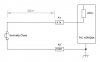
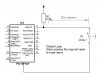
I need to connect 8 panic switches to PIC 8 inputs & make an alarm when one or more is activated.Also I'm showing the corresponding zone on a single seven segment display.

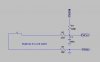
My only doubt is that the inputs are coming from long distance like 30 meters,50 meters max.

What hardware do I have to use?
 

Attachments

  • Closed Loop.JPG
    Closed Loop.JPG
    27.4 KB · Views: 213
There really not anything needed your reading a button and 5 volts is not going to have a great drop even at 50 meters but I would use a 10 k pullup. At 150 feet a 22 AWG has 2.421 ohms resistance
 
Here's how I would do it: R1 pulls up the port pin when the switch is opened. R2-C1 acts as a low-pass filter to shunt RFI (from Cell phones, etc) and static electricity to ground and provides some switch de-bounce. R3 limits the current that a static discharge and RFI can inject into the ground plane under the PIC. If static electricity (charged humans touching the switch resets the PIC), you may have to take more drastic measures.
 

Attachments

  • D16.jpg
    D16.jpg
    25.8 KB · Views: 246
If you use a 74hc147 (or similar part) you will turn 1 or 9 switches into binary. Then use a 7 segment decoder to drive the LEDs. Sorry no PIC but two simple ICs.
 
Here's how I would do it: R1 pulls up the port pin when the switch is opened. R2-C1 acts as a low-pass filter to shunt RFI (from Cell phones, etc) and static electricity to ground and provides some switch de-bounce. R3 limits the current that a static discharge and RFI can inject into the ground plane under the PIC. If static electricity (charged humans touching the switch resets the PIC), you may have to take more drastic measures.

Excellent circuitry I'll use this one.Thats the one I was searching :)

Note that I use a close loop (when the switch opens it will make alarm).In idle state 100K pull up will drain minimum current that will be fine.

I hope I can bypass R3 but in the PCB I'll add a place to that as well.

Thanks for the support.
 
If you read the switch several times with a delay inbewteen, then if you get the same result every time you know the read is valid and not noise fron a cell phone etc.
S imple software filter.
 
Guys I made my hardware like this.I got to know sometimes the PIC detects like open circuit even the switch still closes...!
Does it due to series 4.7K resister?
 

Attachments

  • Switch Input.JPG
    Switch Input.JPG
    14.2 KB · Views: 155
Status
Not open for further replies.

New Articles From Microcontroller Tips

Back
Top