Continue to Site

Welcome to our site!

Electro Tech is an online community (with over 170,000 members) who enjoy talking about and building electronic circuits, projects and gadgets. To participate you need to register. Registration is free. Click here to register now.

  • Welcome to our site! Electro Tech is an online community (with over 170,000 members) who enjoy talking about and building electronic circuits, projects and gadgets. To participate you need to register. Registration is free. Click here to register now.

PIC generating video signal

Status
Not open for further replies.

jhanus

New Member
Hello,

I'm student of electrical engineering, just finished second year.
In one course I took a project where I need to develop a system which generates PAL signal and I have to use it for text and simple picture.

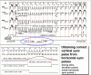
I don't know what I'm doing wrong, but from 64us(one scan line, 52us data) I use first 4us for sync, then 8us for beam position,and that should be enough to create pillars because after every 64us I sent the same data 4us+8us+52us.

I even didn't get to interlacing, and good code. :mad:

Another problem is Vertical Sync, there is no info how to use it,and reading code of **broken link removed** is very hard because of optimization.

So, if anyone has a SIMPLE program that uses a Hsync and Vsync for writing a simple text to get me started.

Thank you! :)

Oh.., I used Feersum miSim DE for TV plugin.
 
Last edited:
Don't know if this will help, but I've seen several projects using AVR to generate video, ATMega8 I think. I remember one site went into great detail on how and why it works. I believe it was from some university student project. I've seen projects for TV test pattern generators, osciloscopes, multimeter, title generator, clock. Maybe www.hackaday.com has a link to some of these.

I realize that you are looking for PIC, but the hardware and process is similar, perhaps you will find the missing little bit to get yours working. PIC assembly is tough to follow, MOVs around too much for me :) .
 
For a start I would suggest you build PicPong exactly as the website, it does work, and works fine (I built it years back) - but any software generation of video is really pushing things somewhat.

Once you've got it working as is, then try modifying it to do what you want.
 
Thanks HarveyH42,
yeah it really moves sometimes :p

www.hackaday.com is interesting page, had it in bookmarks then lost it.
I agree, principle in AVR's and PIC's is the same, but the problem is there is no sample program, just to show simple signal generation.


Hello, Nigel Goodwin

well, I did play PicPong and modify it, got some lines, but when I'm following the program I get stuck on some trivial things as Vsync...I don't see how and when use it, and why just Hsync isn't working.

If anyone has some info, keep 'em coming, please!
 
Some information & questions for you:

a. are you generating one composite video signal or component video signals like R,G,B,VSync and HSync? A composite signal is far more difficult to generate and one with color burst is near impossible with PIC alone. Even an 20MIPS AVR will be struggling in this case.

b. what PIC and what crystal frequency you are using? Do you know how to generate an interrupt of *constant* timing of about 64uS? It can be near 64uS but must be constant without jitter with each line. A simple timer interrupt will not work. You'll need some coding trick to compensate for interrupt latency. Or you can choose to go into SLEEP mode before interrupt occurs.

c. aim for non-interlace 312 line per field instead of full PAL standard which has half line. It is far more difficult to generate.

d. read as many information as you can get from the internet about PAL video format and their timing. How the black and white video level is being represented by an analogue voltage level.

Make sure you understand what equalising pulses are and how to code them into your generated video signals. Without equalising pulses, you won't get vertical sync in a composite signal and therefore no chance of a stable TV display.

e. start with generating a full width white video line for all 312 lines, then do some coding to generate half width, half width left top half and half width bottom right half to get two squares......

f. if all else fails, curse yourself on why you have agreed to work on such difficult/challenging project. :D
 
Thanks guys,

1) I'm generating black, white, Hsync, Vsync with '2bit DA'(and grey,but can't use it)

2) Any PIC from family PIC16 (currently PIC16F84 because mostly code is for this PIC), frequency is 12MHz, that means one cycle 0.33..us

I don't understand "interrupt of *constant* timing", I wrote part of code to generate 4us for Hsync, then 8us delay(black) and 52us of data(white and black).
More simple can't go ,but it just isn't working.
I tested every part of code and it has perfect timing. (if 12MHz is 12MHz)

3) Well I'm going to use when finished interlacing because of flickering. Now I'm at half of PAL, like said 312 scanlines.

4) I don't know what equalising pulses are so that could be a problem.

5) Tried but it's not working, probably I should use directly TV and not simulator.

6) Ahh, I realized it's in my nature to torture myself. :rolleyes:
 
12Mhz PIC running frequency is a max of 3 million instructions per second .....

Dont forget that the MIPs of the PIC is Fosc / 4

I don't know if that helps at all.
 
picbits said:
12Mhz PIC running frequency is a max of 3 million instructions per second .....

Dont forget that the MIPs of the PIC is Fosc / 4

I don't know if that helps at all.

Not really, in his previous post he quoted 0.33uS per instruction.
 
jhanus said:
1) I'm generating black, white, Hsync, Vsync with '2bit DA'(and grey,but can't use it)

If you separate out the HSync and VSync from the video signal, it is much easier to generate than a composite signal. You will then need three separate connections to the TV or monitor.

I don't understand "interrupt of *constant* timing", I wrote part of code to generate 4us for Hsync, then 8us delay(black) and 52us of data(white and black).

The usual method is to generate a *constant* timer interrupt for the HSync signal to start with, using a PIC timer. In real life, the HSync signal occurs regularily and does not varies with time. Therefore it is a really good idea to generate it first and use it as reference for the rest of the video line. You can base everything else on the start of this interrupt signal like outputting the width of the HSync pulse, wait and outputting the analoge level like black or white.

Well I'm going to use when finished interlacing because of flickering. Now I'm at half of PAL, like said 312 scanlines.

If you goes the interlace path, then your code will be more complex. I'll show you a picture. Notice the area circled blue, for interlace mode, the even field VSync needs to be outputted at the time in between the middle the two successive HSync pulses.

4) I don't know what equalising pulses are so that could be a problem.

You don't need equalising pulses if you generate the VSync by code separately. Real life TV signal need them because the VSync can't be sent separately but have to be embedded as part of the transmitted video signal.
 

Attachments

  • V_Sync.gif
    V_Sync.gif
    34.9 KB · Views: 670
Last edited:
Thanks,

My initial idea was to use connection like in this **broken link removed**, so that I use one pin as 'static' which changes only for sync, another port as shift register to obtain higher resolution. And probably if I use this variant, equalising pulses will be a must?
But if separate connections are simpler than first I will use that method.

To use interrupt for the HSync signal seems as a good idea, but isn't there a latency to get to interrupt and limit to interrupts in specific time, although 64us is more than enough.

I see that interlacing for now isn't an option, but why are on that picture 4 fields, a picture is divided in two fields, odd and even?
Also from where is that picture maybe I can get some info there.

**broken link removed** to some info about TV signals.
 
Last edited:
jhanus said:
To use interrupt for the HSync signal seems as a good idea, but isn't there a latency to get to interrupt and limit to interrupts in specific time, although 64us is more than enough.

There are two methods to correct for the latency. The first one is putting the PIC into SLEEP and use timer interrupt to wake it up. This would give you constant latency as the PIC is not executing instruction while sleeping. The second method is to read the timer count value and make necessary correction in the number of instructions that immediate follows. Recently there is a thread on this very topic in this forum. For example, when in interrupt, one wait 10 instructions cycle before outputting to port pin for HSync. If while in interrupt and one reads the timer count and obtains a value of 4, then just wait 6 more cycles before changing the pin level. Or if one gets 6, then wait 4 more cycles. You'll get the idea.

jhanus said:
I see that interlacing for now isn't an option, but why are on that picture 4 fields, a picture is divided in two fields, odd and even?

If you looked closely, you will see there is a sine wave between HSync_Pulse 9th and 10th. This denotes the phase of the color burst but it would not concern you as you are not using color. Field 3 and 4 is just the repeat of field 1 and 2, only difference is the phase of the color burst changes.

Also from where is that picture maybe I can get some info there.

Unfortunately, that image has been taken from the 2005 archive of my harddrive and I cannot locate where it originates from. Sorry for that.

How one would wish there is a search engine for image, just send part of the image and you get the hits.
 
Thanks,
for the info about guys.

I will use one of the two methods for correcting latency in interrupt, though I will lose some precious microsecond.

Now I'm off to reading, expect results soon,or questions, whatever comes first. (on the part with results look relatively :rolleyes: )


Offtopic:
eblc1388 said:
How one would wish there is a search engine for image, just send part of the image and you get the hits.

Ha, the same thing I was thinking about music, but humming in mic and today voice recognition, don't think so, although it would be nice.
 
Status
Not open for further replies.

New Articles From Microcontroller Tips

Back
Top