Continue to Site

Welcome to our site!

Electro Tech is an online community (with over 170,000 members) who enjoy talking about and building electronic circuits, projects and gadgets. To participate you need to register. Registration is free. Click here to register now.

  • Welcome to our site! Electro Tech is an online community (with over 170,000 members) who enjoy talking about and building electronic circuits, projects and gadgets. To participate you need to register. Registration is free. Click here to register now.

PIC Controlling PSP Joystick

Status
Not open for further replies.

AtomSoft

Well-Known Member
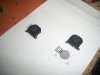
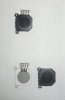
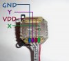
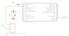
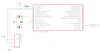
Hey guys i have people ask me now and then how to get data from PSP JoyStick... Where here is some pic code i made. I will draw a schematic in 10 minutes and also a small video and pictures of exact pinout... I hope you will appreciate and enjoy this info... At the end ill create a PDF with code and images for easy portability...

Code:
/* *****************************************************************************
;                                                                              *
;    Filename: PSP JOYSTICK CONTROL (PIC18F2525)(40MHZ)(10MHZ x 4PLL)          *
;    Date: FEB, 20 - 2010                                         	           *
;    File Version: 001                                                         *
;                                                                              *
;    Author:   Jason Lopez                                                     *
;    Company:  AtomSoft                                                        *
;                                                                              *
;***************************************************************************** */

#include <p18f2525.h>
#include <delays.h>
#include <string.h>

#pragma config WDT = OFF, LVP = OFF, OSC = HSPLL

#define PSPY TRISAbits.TRISA0
#define PSPX TRISAbits.TRISA1

#define YPIN 0
#define XPIN 1

/************************************
Prototypes
*************************************/
void main(void);
void SetupADC(char PIN);
unsigned int GetADC(char PIN);
void SendToPC(unsigned rom char *string);
void SetupUART(void);

/************************************
Variables and Defines
*************************************/
unsigned int XMAIN = 0;
unsigned int YMAIN = 0;
/************************************
Main
*************************************/
void main(void){
volatile unsigned int YDATA = 0;
volatile unsigned int XDATA = 0;

	SetupUART();

	PSPY = 1;
	PSPX = 1;

	Delay10KTCYx(100);
	XMAIN = GetADC(XPIN);

	Delay10KTCYx(100);
	YMAIN = GetADC(YPIN);

	while(1){
		XDATA = GetADC(XPIN);
		YDATA = GetADC(YPIN);

		if(XDATA < (XMAIN - 230)) {
			SendToPC((unsigned rom char*)"RIGHT");
		}
		if(XDATA > (XMAIN + 257)) {
			SendToPC((unsigned rom char*)"LEFT ");
		}
		if(YDATA < (YMAIN - 257)) {
			SendToPC((unsigned rom char*)"UP   ");
		}
		if(YDATA > (YMAIN + 257)) {
			SendToPC((unsigned rom char*)"DOWN ");
		}

	}
}

void SetupADC(char PIN){
    ADCON0 = PIN<<2;                  
    ADCON1 = 0x0D;                  
    ADCON2 = 0b10001101;            
    ADCON0bits.ADON = 1;            
}

unsigned int GetADC(char PIN){
	SetupADC(PIN);
	Delay10TCYx(100);
    ADCON0bits.GO = 1;          //Start the conversion
    while(ADCON0bits.DONE);     //Wait until it’s done
	return ADRES;
}

void SendToPC(unsigned rom char *string){
	Delay10TCYx(100);

	while(*string){
    	while(!PIR1bits.TXIF)     //wait until TXIF is high
        	continue;  
    	TXREG = *string++;    //put byte into Transmit Register  
	}
}

void SetupUART(void){
    TRISC  = 0b10000000;
    TXSTAbits.SYNC = 0; 
    BAUDCTLbits.BRG16 = 0;
    TXSTAbits.BRGH = 1;
	SPBRG = 129;     //19200bps for 40 Mhz

    RCONbits.IPEN = 1;

    TXSTAbits.TXEN = 1;  //ENABLE TX
    RCSTAbits.CREN = 1;  //ENABLE RX
    RCSTAbits.SPEN = 1;  //ENABLE SERIAL PORT and PIN Config

    PIR1   = 0x00;
    IPR1   = 0b00101000;


	Delay10TCYx(100);

}
 

Attachments

  • PSPHYPER..jpg
    PSPHYPER..jpg
    157.9 KB · Views: 287
Last edited:
Quick Rough Draft... I dont have a 18F2525 Part in Eagle... maybe ill update this tomorrow with new part... But heh its a start.. The PSP Part can be found in Sparkfun Eagle Library.
 

Attachments

  • schem..png
    schem..png
    12 KB · Views: 319
I'll post my Eagle part for this. I took a look at the SFE part and it just has the pads and a general outline of the part. I made mine before SFE put the part in its library. Mine actually has a well defined outline of where the part is going to sit, along with holes defined in the correct places for the two mounting holes on the package. The labels on the symbol aren't as nice, though. I didn't make this pretty, but I needed to have the proper package outline for placing it on a board and this might help someone.

Also, watch out if you want to reflow it or hot air it. The part I did this on still worked, but the movement of the stick was not smooth anymore. Also don't wash it, if you are washing your board. There's grease inside it.

Unfortunately, .lbr extension isn't an attachment option and I'm not going to ZIP it just for this, so here's a link.
**broken link removed**
 
Last edited:
Thanks i just downloaded it and going to take a look. Im sure its way better heh... ill change the PDF and scematic with it... Thanks again!!! Do you mind if i host the part online for others to download?
 
Hey mark Dont be mad! but i edited the part. So it has the X,Y and GND,VDD.. heres a screen shot:
 

Attachments

  • PSP_SCHEM..png
    PSP_SCHEM..png
    11.9 KB · Views: 225
It's yours to do what you want with it. All I cared about was the proper outline and the correct placement on the mounting holes so everything else is pretty rough.
 
Here is a updated code which include corners... Like
UP, UP-RIGHT, RIGHT-UP
RIGHT,RIGHT-DOWN,DOWN-RIGHT
DOWN,DOWN-LEFT,LEFT-DOWN
LEFT,LEFT-UP,UP-LEFT

psp_hyper2-jpg.39277

Code:
/* *****************************************************************************
;                                                                              *
;    Filename: PSP JOYSTICK CONTROL (PIC18F2525)(40MHZ)(10MHZ x 4PLL)          *
;    Date: FEB, 20 - 2010                                         	           *
;    File Version: 001                                                         *
;                                                                              *
;    Author:   Jason Lopez                                                     *
;    Company:  AtomSoft                                                        *
;                                                                              *
;***************************************************************************** */

#include <p18f2525.h>
#include <delays.h>
#include <string.h>

#pragma config WDT = OFF, LVP = OFF, OSC = HSPLL

#define PSPY TRISAbits.TRISA0
#define PSPX TRISAbits.TRISA1

#define YPIN 0
#define XPIN 1

/************************************
Prototypes
*************************************/
void main(void);
void SetupADC(char PIN);
unsigned int GetADC(char PIN);
void SendToPC(unsigned rom char *string);
void SetupUART(void);

/************************************
Variables and Defines
*************************************/
unsigned int XMAIN = 0;
unsigned int YMAIN = 0;
unsigned int DIFF = 160;
/************************************
Main
*************************************/
void main(void){
volatile unsigned int YDATA = 0;
volatile unsigned int XDATA = 0;
volatile unsigned char Corner = 0;

	SetupUART();

	PSPY = 1;
	PSPX = 1;

	Delay10KTCYx(100);
	XMAIN = GetADC(XPIN);
	Delay10KTCYx(100);
	YMAIN = GetADC(YPIN);

	//GET SECOND SAMPLE
	Delay10KTCYx(100);
	XMAIN = GetADC(XPIN);
	Delay10KTCYx(100);
	YMAIN = GetADC(YPIN);

	while(1){
		XDATA = GetADC(XPIN);
		YDATA = GetADC(YPIN);

		if(XDATA < (XMAIN - DIFF)) {
			if(YDATA < (YMAIN - DIFF)){
				SendToPC((unsigned rom char*)"..RIGHT-UP..");
				Corner = 1;
			}
			if(YDATA > (YMAIN + DIFF)){
				SendToPC((unsigned rom char*)"..RIGHT-DOWN..");
				Corner = 1;
			}
			if(Corner == 1){
				Corner = 0;
			}else{
				SendToPC((unsigned rom char*)"..RIGHT..");
			}
		}
		if(XDATA > (XMAIN + DIFF)) {
			if(YDATA < (YMAIN - DIFF)){
				SendToPC((unsigned rom char*)"..LEFT-UP..");
				Corner = 1;
			}
			if(YDATA > (YMAIN + DIFF)){
				SendToPC((unsigned rom char*)"..LEFT-DOWN..");
				Corner = 1;
			}
			if(Corner == 1){
				Corner = 0;
			}else{
				SendToPC((unsigned rom char*)"..LEFT..");
			}
		}

		if(YDATA < (YMAIN - DIFF)) {
			if(XDATA < (XMAIN - DIFF)){
				SendToPC((unsigned rom char*)"..UP-RIGHT..");
				Corner = 1;
			}
			if(XDATA > (XMAIN + DIFF)){
				SendToPC((unsigned rom char*)"..UP-LEFT..");
				Corner = 1;
			}
			if(Corner == 1){
				Corner = 0;
			}else{
				SendToPC((unsigned rom char*)"..UP..");
			}
		}

		if(YDATA > (YMAIN + DIFF)) {
			if(XDATA < (XMAIN - DIFF)){
				SendToPC((unsigned rom char*)"..DOWN-RIGHT..");
				Corner = 1;
			}
			if(XDATA > (XMAIN + DIFF)){
				SendToPC((unsigned rom char*)"..DOWN-LEFT..");
				Corner = 1;
			}
			if(Corner == 1){
				Corner = 0;
			}else{
				SendToPC((unsigned rom char*)"..DOWN..");
			}
		}

	}
}

void SetupADC(char PIN){
    ADCON0 = PIN<<2;                  
    ADCON1 = 0x0D;                  
    ADCON2 = 0b10001101;            
    ADCON0bits.ADON = 1;            
}

unsigned int GetADC(char PIN){
	SetupADC(PIN);
	Delay10TCYx(100);
    ADCON0bits.GO = 1;          //Start the conversion
    while(ADCON0bits.DONE);     //Wait until it’s done
	return ADRES;
}

void SendToPC(unsigned rom char *string){
	Delay10TCYx(100);

	while(*string){
    	while(!PIR1bits.TXIF)     //wait until TXIF is high
        	continue;  
    	TXREG = *string++;    //put byte into Transmit Register  
	}
}

void SetupUART(void){
    TRISC  = 0b10000000;
    TXSTAbits.SYNC = 0; 
    BAUDCTLbits.BRG16 = 0;
    TXSTAbits.BRGH = 1;
	SPBRG = 129;     //19200bps for 40 Mhz

    RCONbits.IPEN = 1;

    TXSTAbits.TXEN = 1;  //ENABLE TX
    RCSTAbits.CREN = 1;  //ENABLE RX
    RCSTAbits.SPEN = 1;  //ENABLE SERIAL PORT and PIN Config

    PIR1   = 0b00000000;
    //PIE1   = 0b00101000;
    IPR1   = 0b00101000;
    //INTCON = 0b11000000;

	Delay10TCYx(100);

}
 

Attachments

  • PSP_HYPER2..jpg
    PSP_HYPER2..jpg
    300 KB · Views: 506
Last edited:
Ok i made yet another mod... this time its to control the mouse. Here is my PSP Mouse Joystick...
PIC Code mainly sends 1,2,3,4 for direction. Nice and simple ... any pic with ADC and UART can be used... (or SOFT UART)
PC is expecting COM1 @ 19200bps
PIC CODE:
Code:
/* *****************************************************************************
;                                                                              *
;    Filename: PSP JOYSTICK CONTROL (PIC18F2525)(40MHZ)(10MHZ x 4PLL)          *
;    Date: FEB, 20 - 2010                                         	           *
;    File Version: 001                                                         *
;                                                                              *
;    Author:   Jason Lopez                                                     *
;    Company:  AtomSoft                                                        *
;                                                                              *
;***************************************************************************** */

#include <p18f2525.h>
#include <delays.h>
#include <string.h>

#pragma config WDT = OFF, LVP = OFF, OSC = HSPLL

#define PSPY TRISAbits.TRISA0
#define PSPX TRISAbits.TRISA1

#define YPIN 0
#define XPIN 1

/************************************
Prototypes
*************************************/
void main(void);
void SetupADC(char PIN);
unsigned int GetADC(char PIN);
void SendToPC(unsigned rom char *string);
void SetupUART(void);
void SendCharToPC(unsigned char BYTE);
/************************************
Variables and Defines
*************************************/
unsigned int XMAIN = 0;
unsigned int YMAIN = 0;
unsigned int DIFF = 160;
/************************************
Main
*************************************/
void main(void){
volatile unsigned int YDATA = 0;
volatile unsigned int XDATA = 0;
volatile unsigned char Corner = 0;

	SetupUART();

	PSPY = 1;
	PSPX = 1;

	Delay10KTCYx(100);
	XMAIN = GetADC(XPIN);
	Delay10KTCYx(100);
	YMAIN = GetADC(YPIN);

	//GET SECOND SAMPLE
	Delay10KTCYx(100);
	XMAIN = GetADC(XPIN);
	Delay10KTCYx(100);
	YMAIN = GetADC(YPIN);

	while(1){
		while(1){
			XDATA = GetADC(XPIN);
			YDATA = GetADC(YPIN);
	
			if(XDATA < (XMAIN - DIFF)) {
				SendCharToPC(4);
				break;
			}
			if(XDATA > (XMAIN + DIFF)) {
				SendCharToPC(3);
				break;
			}
	
			if(YDATA > (YMAIN + DIFF)) {
				SendCharToPC(2);
				break;
			}
	
			if(YDATA < (YMAIN - DIFF)) {
				SendCharToPC(1);
				break;
			}
		}
	}
}

void SetupADC(char PIN){
    ADCON0 = PIN<<2;                  
    ADCON1 = 0x0D;                  
    ADCON2 = 0b10001101;            
    ADCON0bits.ADON = 1;            
}

unsigned int GetADC(char PIN){
	SetupADC(PIN);
	Delay1KTCYx(100);
    ADCON0bits.GO = 1;          //Start the conversion
    while(ADCON0bits.DONE);     //Wait until it’s done
	return ADRES;
}
void SendCharToPC(unsigned char BYTE){
	Delay1KTCYx(60);
   	while(!PIR1bits.TXIF)     //wait until TXIF is high
       	continue;  
   	TXREG = BYTE;    //put byte into Transmit Register  
}
void SendToPC(unsigned rom char *string){
	Delay10TCYx(100);

	while(*string){
    	while(!PIR1bits.TXIF)     //wait until TXIF is high
        	continue;  
    	TXREG = *string++;    //put byte into Transmit Register  
	}
}

void SetupUART(void){
    TRISC  = 0b10000000;
    TXSTAbits.SYNC = 0; 
    BAUDCTLbits.BRG16 = 0;
    TXSTAbits.BRGH = 1;
	SPBRG = 129;     //19200bps for 40 Mhz

    RCONbits.IPEN = 1;

    TXSTAbits.TXEN = 1;  //ENABLE TX
    RCSTAbits.CREN = 1;  //ENABLE RX
    RCSTAbits.SPEN = 1;  //ENABLE SERIAL PORT and PIN Config

    PIR1   = 0b00000000;
    //PIE1   = 0b00101000;
    IPR1   = 0b00101000;
    //INTCON = 0b11000000;

	Delay10TCYx(100);

}

Im Uploading the VIDEO now on YouTube...

EDIT:

https://www.youtube.com/watch?v=zniYWLsJsCA

I will add some buttons later to make it simulate Right and Left Mouse Click so you can use it as a actual mouse heh
 
Last edited:
Nice work. Ya, I have it somewhere. I need to reinstall Eagle to extract it from my main library. Got a new computer running today and couldn't just swap over the boot drive so I needed to reinstall Windows.
 
Last edited:
heh busy day today... just finished building my daughters crib... shes due 2/11/11 :D

Here are the pictures i said i was going to post...
 

Attachments

  • pspjoy1.jpg
    pspjoy1.jpg
    56.5 KB · Views: 187
  • pspjoy2.jpg
    pspjoy2.jpg
    17.5 KB · Views: 156
I dont use soldering iron for this part... i do a little trick... i presolder both pads then i preheat the board with heat gun and simply place part and heat for short time... but i will extend pads too.. seems more usefull
 
Status
Not open for further replies.

Latest threads

New Articles From Microcontroller Tips

Back
Top