samcheetah
New Member
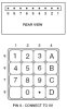
has anyone built the "PIC controlled intruder alarm" from the April 2002 issue of EPE. well ive set onto building this project and i have some difficulties. the first is the hex keypad it uses. its quite different from the hex keypads ive seen on the internet. ive attatched the picture of the keypad.
this is quite different to the keypad at nigel's website on the page.
and i have one more question. what should i use for a strobe.
this is quite different to the keypad at nigel's website on the page.
and i have one more question. what should i use for a strobe.