Continue to Site

Welcome to our site!

Electro Tech is an online community (with over 170,000 members) who enjoy talking about and building electronic circuits, projects and gadgets. To participate you need to register. Registration is free. Click here to register now.

  • Welcome to our site! Electro Tech is an online community (with over 170,000 members) who enjoy talking about and building electronic circuits, projects and gadgets. To participate you need to register. Registration is free. Click here to register now.

PIC circuit problem?

Status
Not open for further replies.

tboydva

Member
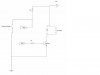
I give up! I can't seem to figure what could be wrong with this circuit... I'm using a 16F628A to "lengthen" a contact closure for an instrument start signal. The closure lasts for 500 msec, but I've determined that it needs to be a least a second to start my other instrument. So, I created the attached circuit so that there's a 5V signal at RB0 until the contact closure occurs. When the closure occurs and RB0 goes low, I'm trying to have RB1 (and RB2) go high to drive a relay and an LED (just to give confirmation). I built this on a breadboard and used the headers on my EasyPIC4 (**broken link removed**. I used pull-down resistors on all unused ports. It worked without issue. I then put the components on this: https://www.melabs.com/downloads/pp18_06.pdf. It works intermittently (but mostly does not). I can monitor the voltage on RB0 and it's 5V, then goes low during a contact closure. All unused ports are pulled low with 1K resistors. RB1 is shown on attached circuit diagram. RB2 drives an LED. The weird thing (at least to me) is that both RB1 and RB2 are about 35 mV when tested with a multimeter. I've tried to look for "bad" connections, but don't seem to see any? The one thing I don't have is a capacitor between Vcc and Vss? Could that be the cause? I'm using an LM7805 regulator for the +5V supply. I can make this on a breadboard and it's works perfectly??? I can't figure out what to try next! Here's the programming code in case it's relevant:

Code:
void main()
{

 //PORTB is all output except F0
 TRISB = 0x01;
 //PORTA is all outputs
 TRISA = 0x00;
 //PORTB starts with bit 0 high
 PORTB = 0x01;
 //PORTA is all low
 PORTA = 0x00;
 do
  {
    //If PORTB.F0 goes low (contact closure)
    if (PORTB.F0 == 0)
    {
    //Make PORTB.F0 high for 1500 ms
    PORTB.F1 = 1;
    //Make PORTB.F1 high also to drive an LED
    PORTB.F2 = 1;
    Delay_ms(1500);
    //Now make PORTB.FO/F1 low again
    PORTB.F1 = 0;
    PORTB.F2 = 0;
    PORTB.F0 = 1;
    }
  }
  //Loop forever
   while(1);
 }
 

Attachments

  • signal.jpg
    signal.jpg
    21.3 KB · Views: 135
Do you have LVP (Low Voltage Programming) turned off in the configuration fuses? Or if not, do you have the RB4/PGM pin (pin 10) pulled low to prevent accidently entering low voltage programming mode on power up or reset?

Other things to look for;

(1) do you have a 0.1 uf bypass capacitor connected close to the VDD and VSS pins?

(2) are you trying to run a crystal oscillator on a solderless breadboard?

(2) do you have MCLR enabled, and if so do you have the pin pulled up to VDD?

Good luck. Mike
 
Your first link doesnt seem to work!!

anyway, IF the circuit worked well on the first board, it should work on the second board!!

anyway check these...

1) Remove the connections to the relay and the LEDs @portB.1 and portB.2
2) Close the switch and monitor the values @ portB.1 and portB.2

3)if it works properly, check if you have connected the transistor properly..
4)Check if the relay is rated for 5V
5)Since the relay is driven from the same supply, the bypass cap is a MUST!!!
6)Preferably, connect the indicator LED in the sinking mode, so you will have to clear PortB.2 to light it up!!

7)If the circuit is not working properly after (2), there is a problem with the board, or the program.(or the way you burnt it)
8) output a random value to PORTB (say, 0x55) and check if it appears @ the port.
9)if it doesnt, come back!!!
 
Mike,

Thanks for the rapid response... For Q1, no I don't! I think I'm going to have to put this in... I know on my development board, there is a cap between Vdd and Vss. I'll put that in. For Q2, I was using the oscillator on the dev board (it has headers for PORTB). I took wires from the PORTB header to my breadboard, so I just have the circuit that I attached on the BB. As for Q3, I'll have to check! I have my dev system at home, so I'll double check. From what I can tell, I have LVP turned off (from my project settings in MikroC). There is a setting for MCLRE_OFF which I don't have checked. Perhaps I need to do that too! I'll give these things a try and see how I fare. Thanks again!

TOm
 
Is the PIC actually running on the breadboard? I'd blink the LED once a second or so to make sure.

Which 7805 are you using? the protoboard look like it takes a to92 package for an L which is rated for 100 mA. If the relay draws more than that, you could be overheating. What is the relay coil resistance? When you turn on the transistor/relay + LED/resistor, they might pull the supply voltage down and reset the PIC?

What happens if you disconnect the relay?

When you say you don't have a cap between Vcc andVss, do you mean a bypass cap or a filter cap? I would make sure I have both. The filter cap should be a couple 100 uFd (C4 in the MELabs schematic). Bypass of 100n near the PIC leads.

Also, make sure that the kickback diode is wired in correctly. Without it you could damage the PIC.

There are a number of ways to cause the PIC to reset - Blink your LED a couple of times on start-up. that way you know if it's a reset problem.
 
Thanks all for the suggestions. I've tried a number of them (added capacitor between Vcc and Vss). Philba, the filter capacitor is already there (I got the PICproto parts kit with the dev board). Tried unhooking the LED and relay, but still have the same problem. I may have figured it out though... I knew as soon as I posted here, I'd figure out some careless mistake. I'm not sure, so I'm going to try one other thing tonight. I'll admit my stupidity if I'm correct - otherwise, I'll REALLY need more help! Thanks so far...

Tom
 
Fixed! Thanks everyone for the troubleshooting help... I thought I made a really careless mistake (which I did), but that wasn't the issue. After I got my C code the way I wanted it, I created a "new" project and imported the C file... Well, I forgot to change the crystal frequency from 8 to 4 MHz (what I had on the MElabs board). I changed it, but it still didn't work. The change that made the circuit function was disabling MCLR (as Mike suggested). I've been reading a lot on PICs and have several books. I was trying to learn assembly (from Microcontrol'n books), but it's been a rough go... One suggested never using the supplied include files, rather create your own header where you're forced to think about the config directive.... Would'a been best for me here! When I got the EP4 board, I tried the C compiler and even though it's been more years that I'd care to admit, in grad school I was fairly adept in C. Anyway, in MikroC, I hit the default settings for the project (which didn't have MCLR set to off)... Now I know to be more careful!!! Thanks everyone for your rapid and thought provoking suggestions. I always go crazy buying and reading books and the internet before I settle down to work on something (like microcontrollers). Inevitably, it's actually doing that makes you learn (the hard way?)!!!

Tom
 
Don't worry about it. Every item on that list was learned "the hard way" by most of us (grin).

Have fun and enjoy the adventure. Regards, Mike, K8LH
 
Status
Not open for further replies.

Latest threads

Back
Top