williB
New Member
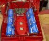
Has anyone ever built a boost converter ( dc to dc )
just curious as the power output of anyones boost.
i think i got about 49Watts at most , at a resonable efficiency , dont remember off hand.
anyone ever boosted 100 Watts , or more?
if so what was the efficiency
i did mine with a 16F877A's PWM
just curious as the power output of anyones boost.
i think i got about 49Watts at most , at a resonable efficiency , dont remember off hand.
anyone ever boosted 100 Watts , or more?
if so what was the efficiency
i did mine with a 16F877A's PWM